Calibration Guide for Total Station Collimation: Inspection and Adjustment of the Photo Reticle
I. Component Overview
In a Total Station telescope system, the photo reticle is the critical physical reference for sighting accuracy. Located within the eyepiece assembly, it consists of high-precision vertical and horizontal crosshairs.
Function: It provides a precise geometric center to establish the Line of Sight (Collimation Axis) for targeting.
Impact of Displacement: Persistent vibrations, thermal expansion, or physical impacts can cause the photo reticle to loosen or rotate. Even a slight tilt in the crosshairs introduces geometric errors (where the vertical axis is not perpendicular to the horizontal axis), leading to inaccurate horizontal and vertical angle readings.
II. Inspection Procedure (Step-by-Step)
Before attempting any adjustment, perform a rigorous inspection in a stable environment:
Setup and Leveling: Mount the Total Station on a stable tripod and perform a precise leveling using the electronic bubble to ensure the instrument’s vertical axis is perfectly plumb.
Target Selection: Choose a clear, distinct, and fixed target Point A (e.g., a lightning rod tip or a dedicated calibration crosshair) at a distance of 10–20 meters.
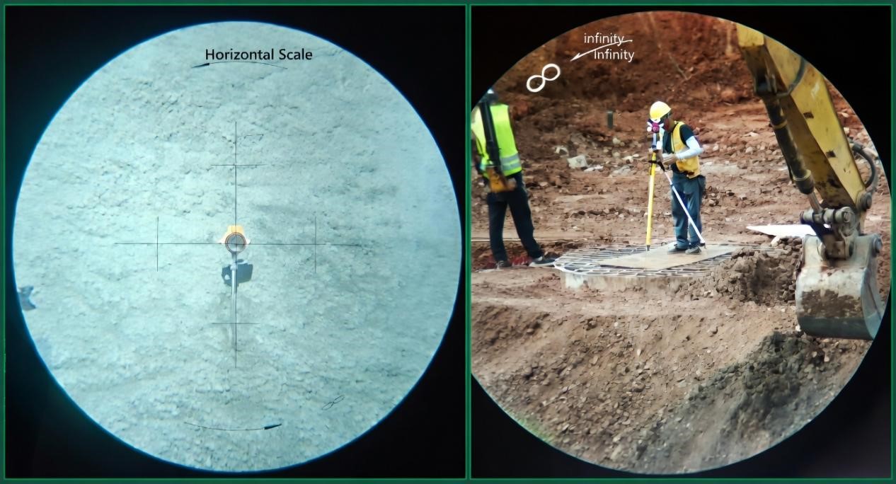
Initial Sighting: Adjust the eyepiece diopter until the crosshairs are sharp, then use the focusing knob to eliminate parallax. Aim the center of the photo reticle crosshairs exactly at Point A, and lock both the horizontal and vertical motion clamps.
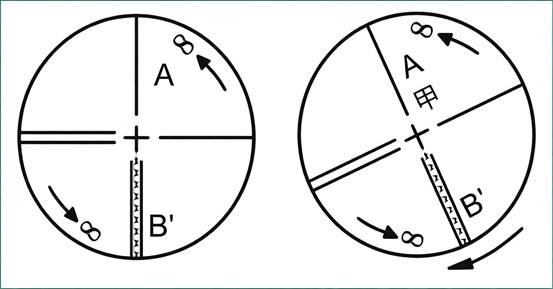
Dynamic Tracking: Slowly rotate the telescope’s vertical tangent screw, moving Point A toward the edge of the field of view (designated as Point A′).
Assessment:
Pass: If Point A moves strictly along the vertical hair, the crosshair orientation is correct; no adjustment is needed.
Fail: If Point A′ deviates from the vertical hair (as shown in the right figure), the crosshairs are tilted, and the photo reticle must be calibrated.

III. Standard Adjustment Process
Note: Calibration should be performed in shaded conditions with stable temperatures to avoid atmospheric refraction.
Expose the Assembly: Unscrew the photo reticle housing cover located between the eyepiece and the focusing knob. This reveals three (or sometimes four) reticle-securing screws arranged around the circumference.
Fine Adjustment:
Using a precision screwdriver, evenly and slightly loosen the three securing screws.
Gently rotate the photo reticle seat around the collimation axis while looking through the eyepiece until the offset Point A′ aligns perfectly with the vertical hair.
Pro Tip: For instruments equipped with lateral calibration screws, follow the “loosen one side, tighten the other” principle to move the reticle incrementally.
Secure and Re-verify: Tighten the securing screws in a cross-pattern. Avoid excessive force, as this can cause secondary displacement or mechanical stress on the reticle.
Recalibration Loop: Repeat the “Inspection” steps. Professional calibration often requires multiple fine-tuning passes to achieve optimal precision.
Final Reassembly: Once verified, reinstall the housing cover securely to prevent dust and moisture from entering the optical path.
IV. Professional Precautions & Maintenance
Brand Variations: The structure and screw count of the photo reticle assembly may vary by manufacturer (e.g., Leica, Topcon, Trimble). Always consult the specific Technical Service Manual for your model.
Error Tolerances: Ensure the residual error remains within the limits of your project’s specifications. Generally, the $|2C|$ (Collimation Error) should be less than 10″.
Environmental Interference: Never calibrate under direct sunlight or during intense ground-heat shimmer, as atmospheric refraction can create a “false offset.”
Expert Service: If you observe internal fungus, moisture, or a jammed mechanical structure, do not disassemble the internal lenses. Contact an authorized service center for clean-room repairs.