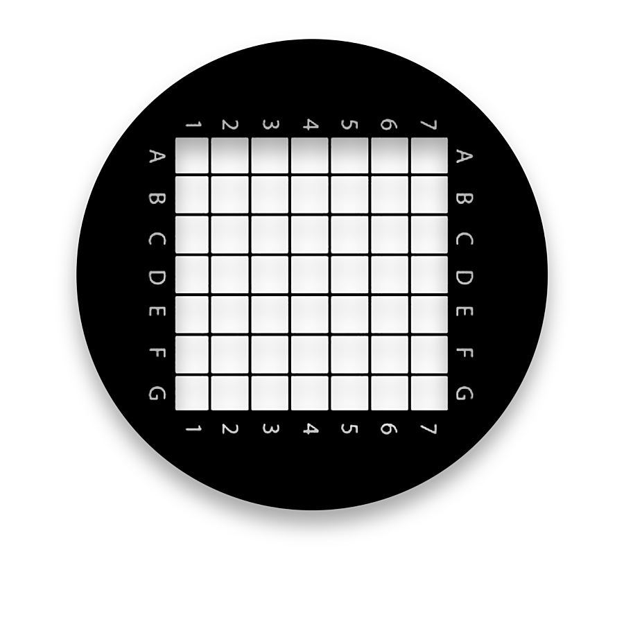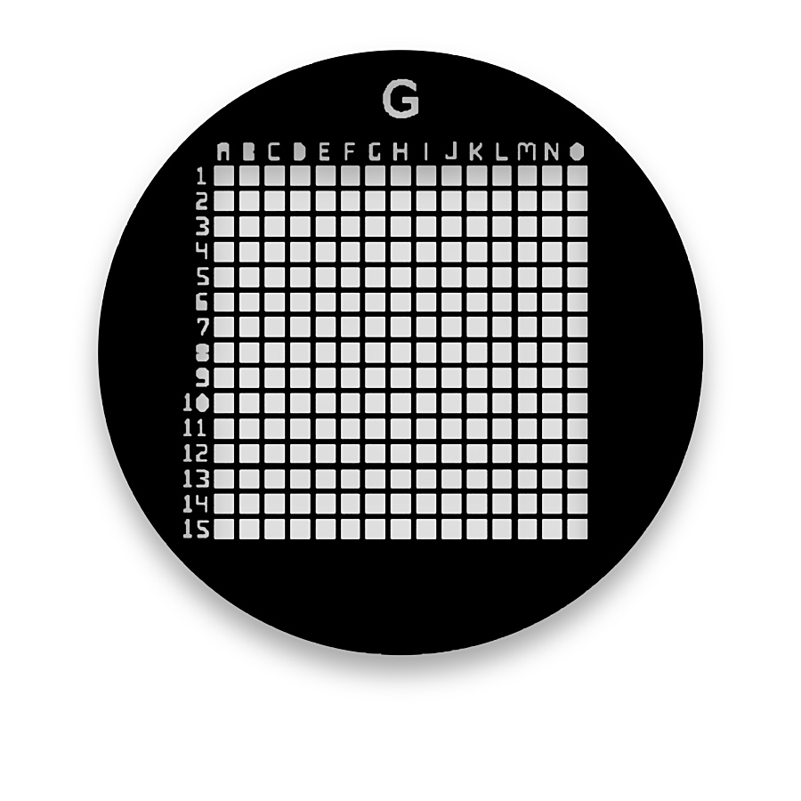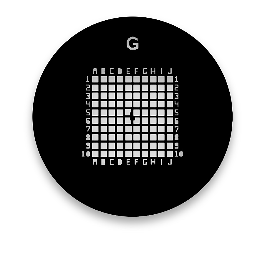
TEM Coordinate Grids

A metal specimen-support grid provides physical openings for transmission electron microscopy. Its bars or surrounding frame support the specimen or a thin support film while leaving observation areas open.

TEM Coordinate Grids

Configuration and materials

Metal grid material, support-film type and compatibility with the specimen preparation method are selected together. A glass substrate is not part of this specimen-grid structure.

  • Outer format and specimen-holder fit
  • Opening geometry, bar width and material
  • Support film and coordinate marks

Balance support and usable observation area

Wider bars provide more support but obscure more of the specimen. Larger openings expose more area but place greater demands on the specimen or supporting film. Mesh count alone does not define the clear opening: bar width also matters.
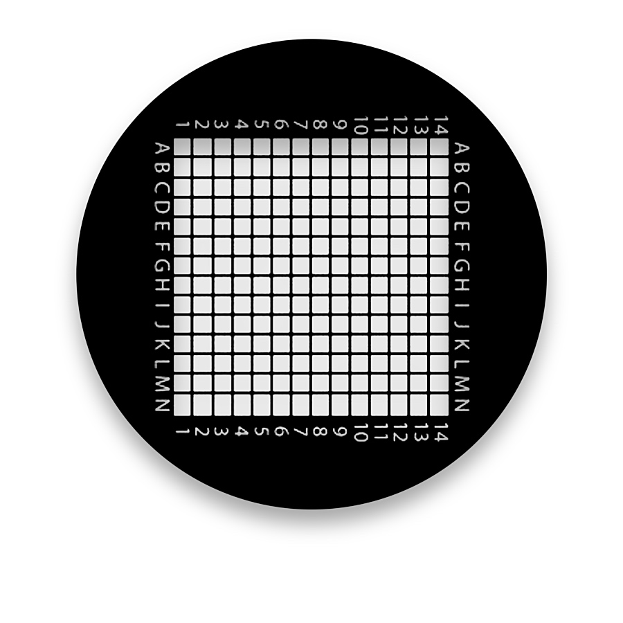
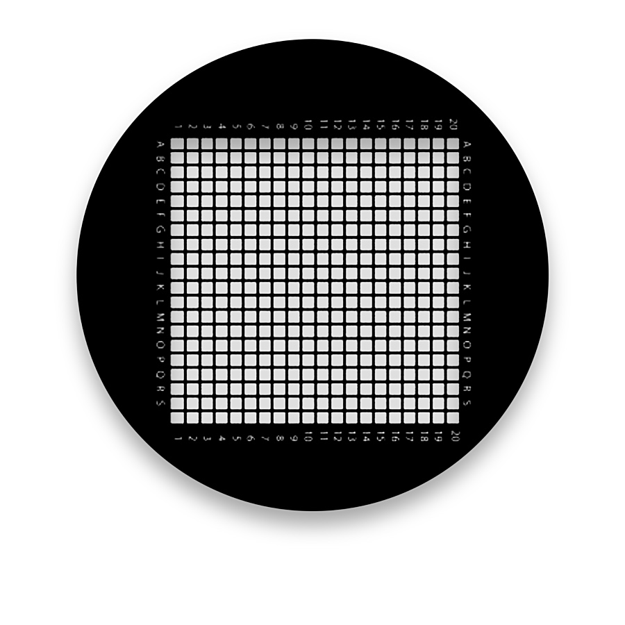
Keep specimen coordinates recoverable

For labelled grids, record both the address and orientation. On an unlabelled regular lattice, record an identifiable reference before moving to another field; repeated cells may otherwise look identical.

Choose by function

What it is and what it does

A metal specimen-support grid provides physical openings for transmission electron microscopy. Its bars or surrounding frame support the specimen or a thin support film while leaving observation areas open.

When to choose it

Choose labelled finder or coordinate grids when recorded specimen regions need to be relocated. Record grid orientation and the local position within the labelled region.

How it differs from related products

A TEM support grid has physical openings. A chrome-on-glass reticle has a continuous optical substrate and serves a different observation or alignment role. Similar lattice geometry does not make the components interchangeable.

What can be customised

Mesh geometry, bar width, outer format, material and any support film determine the configuration. Coordinate marks add an address system without changing the fundamental specimen-support role.

What you receive

The component definition identifies the metal grid and any support-film coating separately. Specimen preparation and the microscope holder remain separate parts of the workflow.

Pattern and format options

TEM Coordinate Grids — 7XC200-002

7XC200-002

TEM Coordinate Grids — 7HX-200

7HX-200

TEM Coordinate Grids — 7HX-300

7HX-300

TEM Coordinate Grids — 7HX-100

7HX-100

TEM Coordinate Grids — 7XC200

7XC200

Common questions

Does mesh count define the open-hole width?

No. The pitch and bar width together determine the physical clear opening.

Related pattern choices

Selection notes

TEM coordinate grids identify specimen regions using a defined coordinate-marking layout.

Confirm labels, orientation and the visible coordinate map with the support structure and film.

Information for your inquiry

Coordinate layout, labels, metal, mesh, support film and holder.

Do coordinates directly give specimen dimensions?

Coordinate marks identify regions. Dimensional measurements require a separately calibrated imaging scale.

Search