

Optical Encoder Discs & Linear Scales
Photolithography-patterned glass encoder discs and linear scales for rotary and linear position feedback. Configure incremental, absolute, code-track and reference-mark patterns with line-width tolerance of ±0.2 µm and mechanical cutting accuracy of ±0.02 mm.
The disc or scale is the passive optical component. Published component values include line-width tolerance of ±0.2 µm and mechanical cutting accuracy of ±0.02 mm. Output signals, interpolation and system accuracy also depend on the readhead, electronics and mounting.
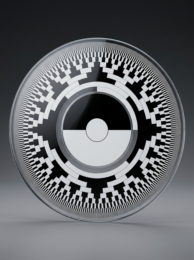
Rotary encoder discs & code patterns


Linear encoder scale types
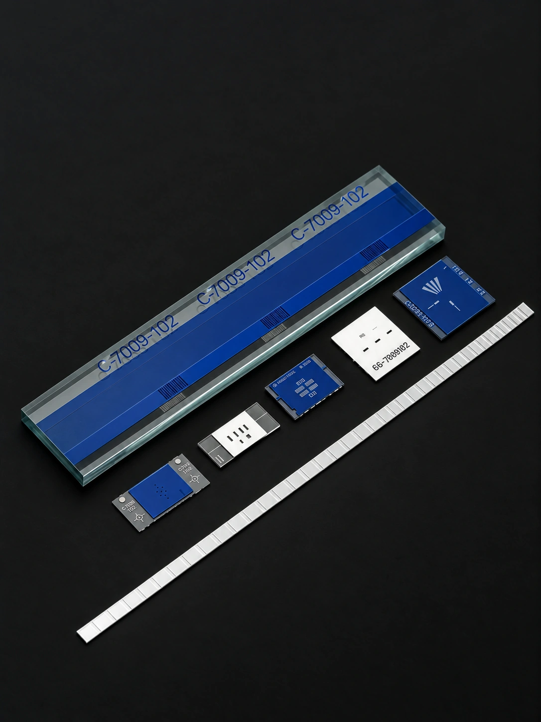
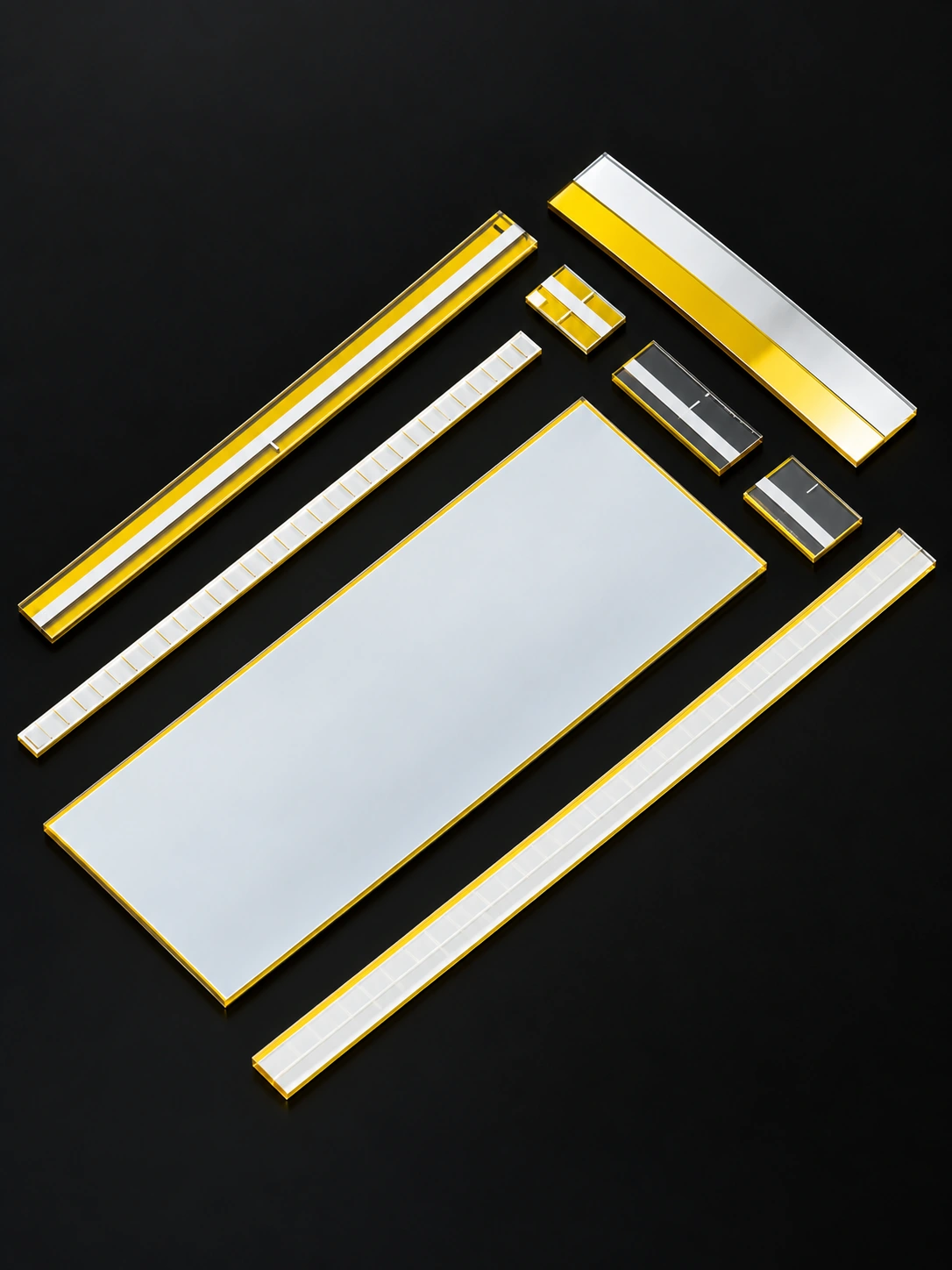
Select the light path first, then the position code. Compare all glass linear encoder scales
Find the right product for the task
| Task or choice | Product route | Why it matters |
|---|---|---|
| Motion geometry | Disc / linear scale | A disc refers to angle; a scale refers to distance along an axis. |
| Position at startup | Incremental / absolute | Incremental counts motion from a reference. Absolute coding identifies a position within its encoded range. |
| Reader access | Transmission / reflection | The light path is independent of the encoding method; match access and optical contrast to the reader. |
| Code compatibility | Gray / natural binary / periodic tracks | The glass pattern must match the decoding architecture; more code bits alone do not guarantee higher system accuracy. |
Bring the selected options into one specification
- Disc or scale dimensions and thickness
- Photolithographic line-width tolerance and mechanical cutting accuracy
- Track layout, pitch and reference marks
- Pattern registration, optical contrast and inspection criteria
Transmissive or reflective: match the optical path.
Incremental and absolute describe how position is encoded. Transmissive and reflective describe how light reaches the detector. Both code families can be configured for either reading geometry when the pattern, coating and readhead are designed together.
Transmissive Glass Encoder Discs
The light source and detector are on opposite sides of the disc. Clear glass regions transmit light; opaque chromium tracks interrupt it. Low-reflectance chromium (LRC) can help reduce stray reflections from the patterned surface.
- Specify clear-area transmission and opaque-track optical density (OD) at the operating wavelength.
- Confirm the patterned face, illumination side, readhead gap and space available on both sides of the disc.
- Choose the substrate for temperature range, dimensional stability and spectral transmission.
Reflective Glass Encoder Discs
The light source and detector are on the same side. The readhead distinguishes regions with different reflectance, which can suit installations with access from only one side. High-reflectance chromium (HRC) and low-reflectance regions are selected to produce the contrast required by the sensor.
- Specify both high and low reflectance at the operating wavelength and incidence angle.
- Define the detector geometry, working distance and signal-contrast requirement.
- Review rear-surface reflections and background treatment to control unwanted light returning to the detector.
Encoder disc design examples
Optical encoder discs
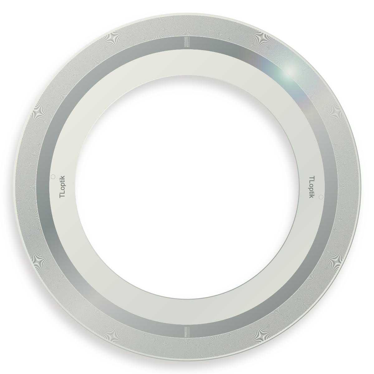
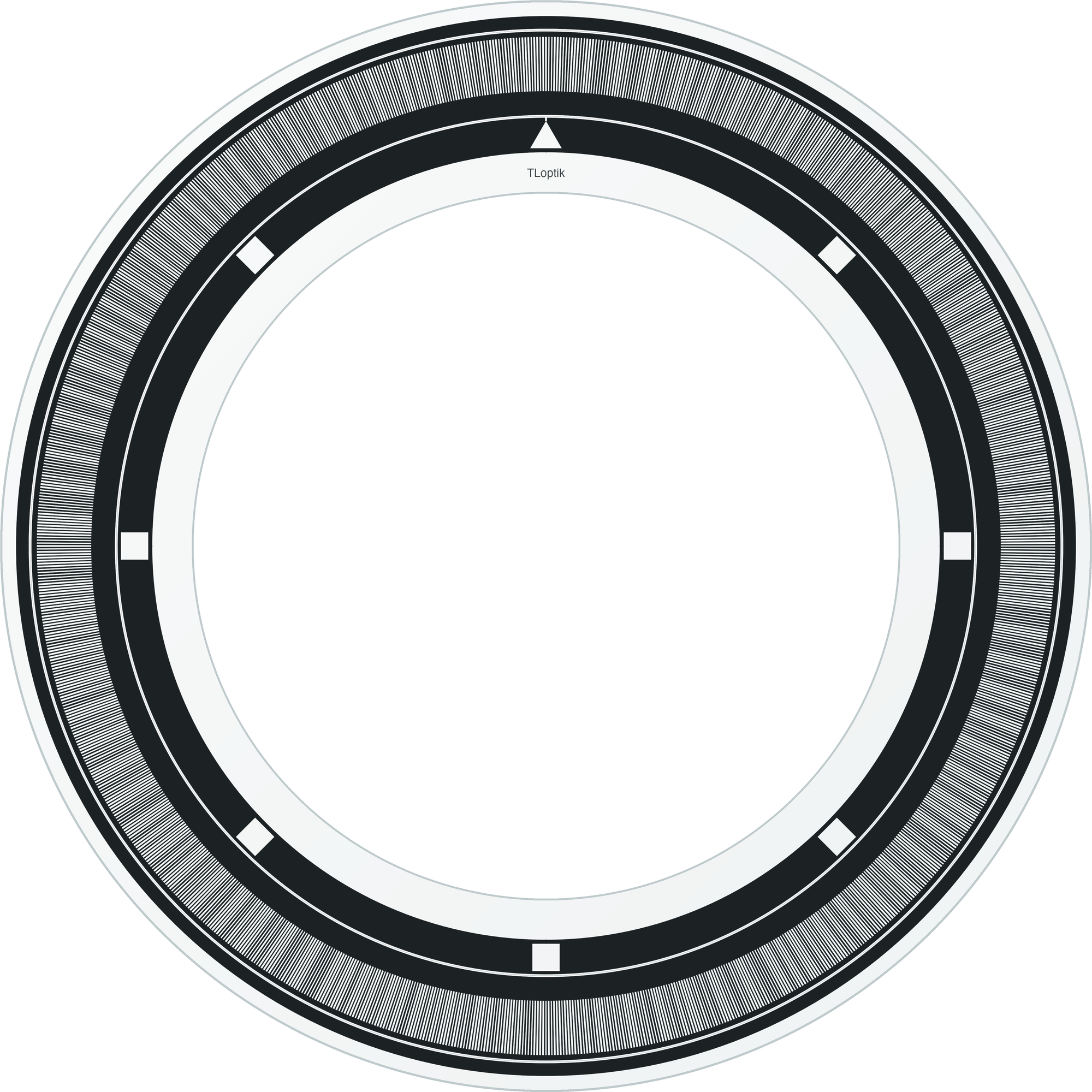
Fine-pattern glass encoder disc
79 mm outer diameter / 51 mm bore / ultra-clear glass
Optical encoder discs
Annular-pattern glass encoder disc
Alternative pattern layout / custom specification
Start with the motion, then define the code.
Choose rotary or linear geometry first. Then choose incremental or absolute sensing, followed by the code convention, optical readout and mechanical datum. This keeps a glass pattern specification separate from the performance of the complete encoder assembly.
Rotary / incremental
Repeating radial tracks report relative angle or speed. Add an index (Z) track when the system needs a repeatable reference after homing.
Explore this configurationRotary / absolute
Coded tracks identify the angular position directly through a compatible readhead and decoder. The code map, bit count and absolute zero must be approved together.
Explore this configurationAbsolute / Gray code
Adjacent Gray-code words change by one bit in the ideal sequence. It is a code convention for an absolute pattern, not a separate mechanical disc format or electrical interface.
Explore this configurationAbsolute / natural binary
Weighted binary tracks identify position directly, but multiple bits may change at a sector boundary. The decoder and readhead must be designed for the approved transition convention.
Explore this configurationLinear / incremental
A repeating pitch measures displacement along an axis. Reference marks establish an origin; electrical output resolution may also depend on interpolation.
Explore this configurationLinear / absolute
A defined code sequence identifies position without an index search. The code map, reading window and decoder convention must match exactly.
Explore this configurationThe disc is one part of a matched optical system.
The pattern must be read with the intended wavelength, illumination geometry, readhead gap and signal threshold. Mechanical runout, bore concentricity and the angular datum influence the result just as the line or code geometry does. Electrical protocols such as incremental A/B output or a downstream serial interface belong to the complete encoder electronics and should not be confused with the glass pattern type.
- Incremental pattern: repeating track, optional index or reference track, defined period and duty cycle
- Absolute pattern: approved code map, bit count, track order and absolute zero
- Optical mode: transmissive or reflective contrast at the working wavelength
- Mechanical interface: outer diameter, bore, thickness, datum and allowable runout
What belongs in the encoder drawing
Define the manufactured pattern separately from the complete encoder performance. A clear drawing lets the pattern, substrate, readhead interface and inspection records be reviewed without relying on an ambiguous product name.
- Disc geometry: outer diameter, bore, thickness, edge and mounting datums
- Pattern geometry: track radii, pitch, line width, duty cycle and reference features
- Code definition: Gray, natural binary or custom map, bit order, reading direction and zero
- Optical and acceptance conditions: wavelength, contrast, placement error, defects and report format
An encoder pattern designed around your readhead.
TL OPTIK manufactures glass encoder discs and linear scales from your pattern specification. From incremental tracks to absolute code patterns, we review pitch, reference marks, optical contrast and mechanical datums together. Tell us how the pattern will be read so the component specification supports your motion system.
Discuss your encoder patternEncoder and scale questions
Is binary code the same as Gray code?
No. Natural binary assigns weighted bits and can change several bits at one boundary. Gray code is arranged so adjacent code words differ by one bit. They require different approved code maps and decoder conventions.
Are A/B, Z, EnDat or BiSS product categories?
A/B and Z describe common incremental signal or reference features, while EnDat and BiSS are electronic communication interfaces. They are system-level requirements and should be specified alongside the glass pattern, not used as interchangeable product names.
Does a higher line count or bit count automatically give higher accuracy?
No. Nominal pattern resolution is only one input. Feature placement, eccentricity, mounting runout, readhead geometry, interpolation and the complete error budget determine system accuracy.
Can the same disc artwork be used in another readhead?
Only after confirming wavelength, optical mode, track spacing, working gap, contrast and reading direction. A similar diameter does not prove optical or electrical compatibility.
Selection notes
Optical encoder discs and linear scales supply patterned references for rotary and linear position feedback.