What the component does
The code pattern is the optical reference for shaft rotation. Its signal format must be compatible with the motor feedback electronics.

Measure motor shaft position so that a servo drive can regulate motion and, with the appropriate architecture, establish commutation position.
The disc is mechanically coupled to the shaft, while the reader stays on the housing.
Incremental signals and an index are not automatically a complete absolute startup or commutation reference.
The code pattern is the optical reference for shaft rotation. Its signal format must be compatible with the motor feedback electronics.
An incremental design usually combines repeated tracks with a reference strategy; absolute coding can support position identification at startup.
Runout, disc tilt and contamination can vary the readout signal over a revolution. Controller performance cannot compensate for every optical reading defect.

Periodic code tracks for angular increments and speed-derived measurements.

Code patterns for servo systems requiring direct position identification.
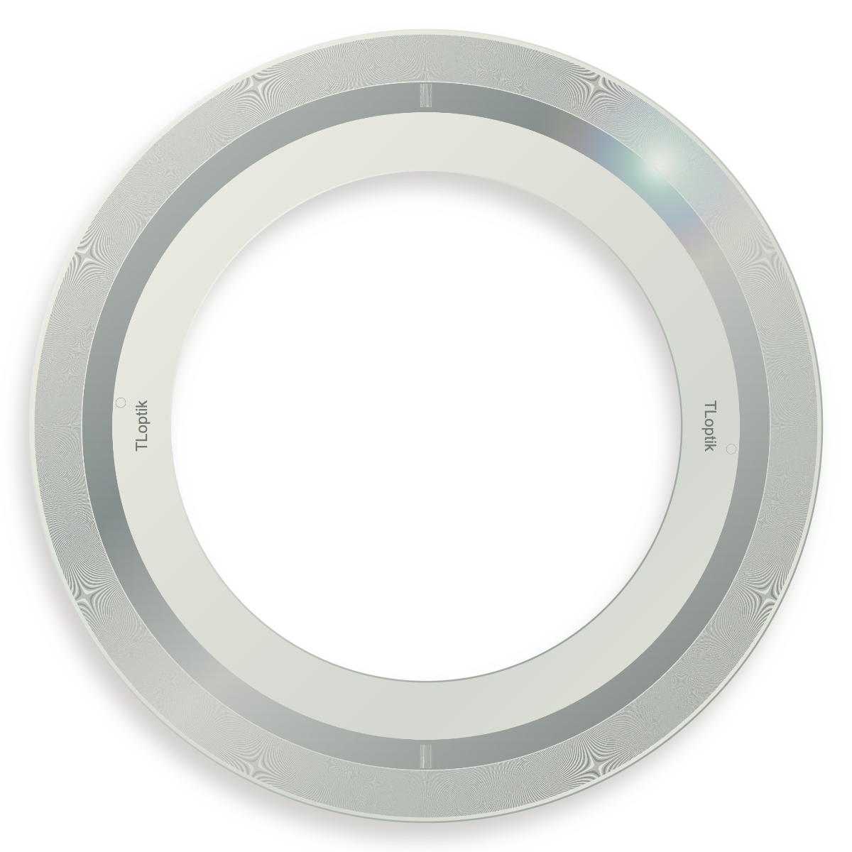
Existing glass disc examples and a starting point for custom track layouts.
A shaft-mounted code disc is read optically as the motor rotates. Repeated tracks support motion feedback; an index track establishes a reference. Code or commutation tracks may be included when required by the motor and readhead design. The disc is the passive pattern, while electrical interfaces are supplied by the encoder system.
Match the optical periods to the readhead and distinguish periods per revolution from pulses or decoded counts. Disc eccentricity, angular pitch error and mounting runout contribute to the feedback error. Confirm speed, mechanical support and operating temperature as part of the assembly design.
The controller derives speed from measured motion and time. A stable, readable periodic pattern supports that estimate, but the disc itself does not output an electrical speed signal. Sensor bandwidth, interpolation and the control algorithm also affect the result.
A servo-motor encoder disc rotates with the shaft and supplies periodic, index or coded references to its readhead.
The passive disc does not generate an electrical protocol on its own; speed estimation and interfaces belong to the encoder and controller.
It depends on the head. Some read phase-offset areas of one periodic track; others use distinct patterns. Manufacture for the actual sensor layout.