What the component does
Periodic divisions provide incremental information; coded tracks support absolute position identification when paired with the intended reader.

Convert shaft or carriage movement into a position reference that a controller can use for feedback.
The drawing shows a rotary arrangement. A linear scale uses relative translation instead of rotation.
The encoder supplies position information; the drive and controller determine how the mechanism responds.
Periodic divisions provide incremental information; coded tracks support absolute position identification when paired with the intended reader.
The pattern pitch, illumination and detector geometry must work together. The scale is a passive optical component within the sensing assembly.
An incompatible pitch, mounting offset or optical contrast can produce unstable signals even when the nominal division count is correct.

Periodic tracks for relative angular movement and index referencing.

Explore code families for direct angular-position identification.
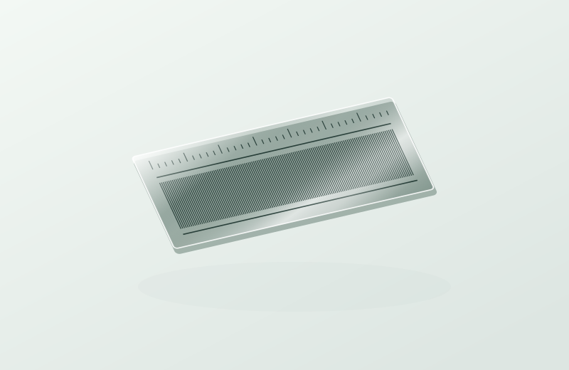
Compare incremental and absolute scales for a linear axis.
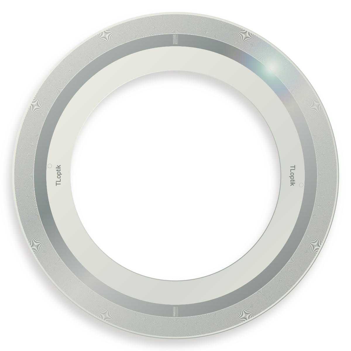
Compare two existing disc design examples before defining a custom rotary pattern.
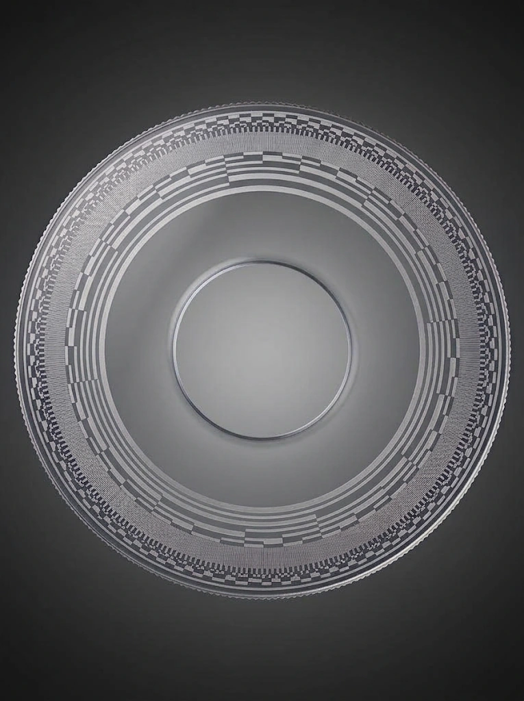
Absolute angular code for a readhead designed for this encoding.
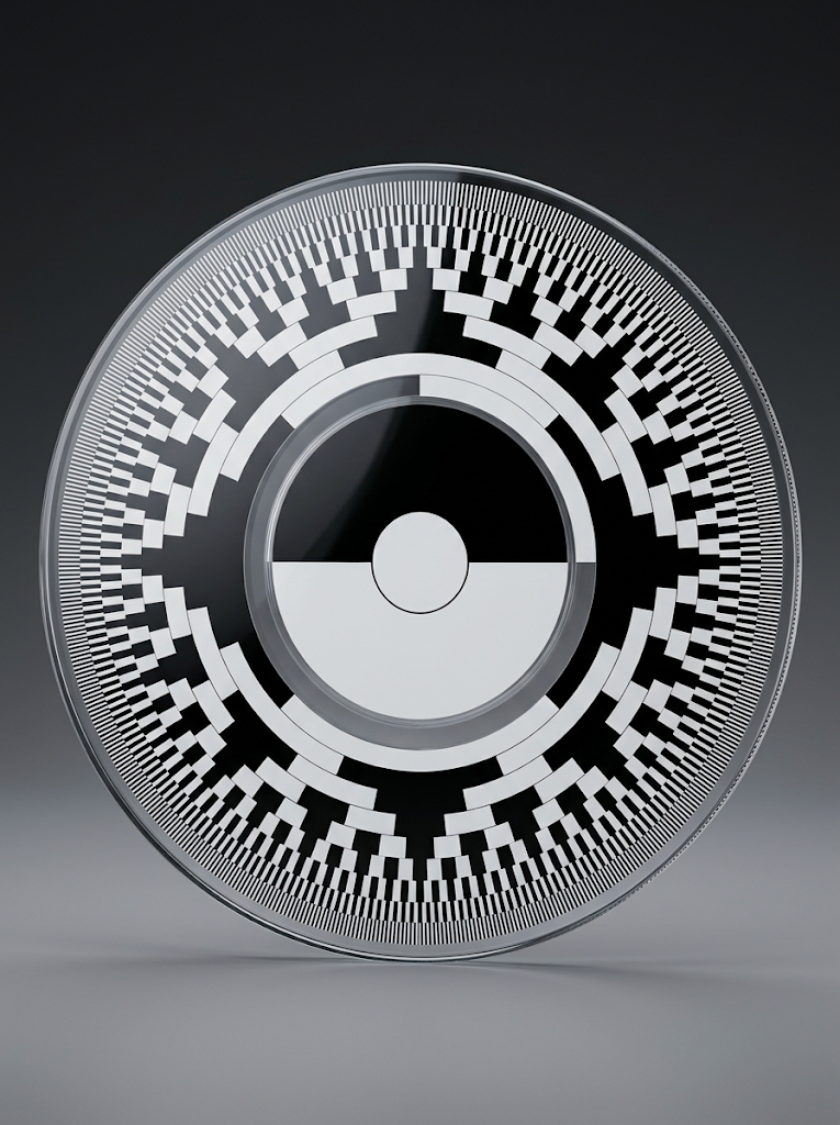
Absolute angular code for a readhead designed for this encoding.
An optical encoder reads a patterned disc or scale to convert mechanical movement into position information. A rotary disc measures shaft angle; a linear scale provides a reference along an axis. These components work with an optical readhead and electronics to form the complete feedback system.
Start with the motion axis and readhead architecture. Incremental patterns provide relative movement and may use an index for homing. Absolute patterns encode position for a compatible decoder. Pattern resolution, installed accuracy and repeatability are separate requirements.
A motor encoder reports motor-shaft movement; a scale on the load can observe motion after a transmission. Selecting where to measure is as important as selecting the code. Backlash and compliance between those locations remain system properties.
Optical encoder discs and linear scales provide position references for motion-system readheads. Rotary axes use discs; linear axes use scales.
The controller uses the resulting signals for feedback. Match optical mode, pitch, reference marks and mechanical installation to the head.
Identical line counts can have different reading radii, pitch, index geometry and head arrangements. Define the optical and mechanical interfaces together.