What the component does
The code disc or ring provides a repeatable reference around the rotation axis, with the readhead mounted to a stable mechanical datum.

Reference a rotary platform directly to its measurement axis for repeatable positioning and angular inspection.
Direct platform measurement can observe output rotation rather than infer it only from a drive motor.
Pattern resolution, mounting accuracy and system calibration contribute differently to the final result.
The code disc or ring provides a repeatable reference around the rotation axis, with the readhead mounted to a stable mechanical datum.
Centre location, track radius and axial clearance connect the optical pattern to the bearing and platform. Some systems use multiple readers to manage selected errors.
More divisions improve nominal reading resolution but do not remove eccentricity or bearing errors. Evaluate repeatability and absolute angle error separately.
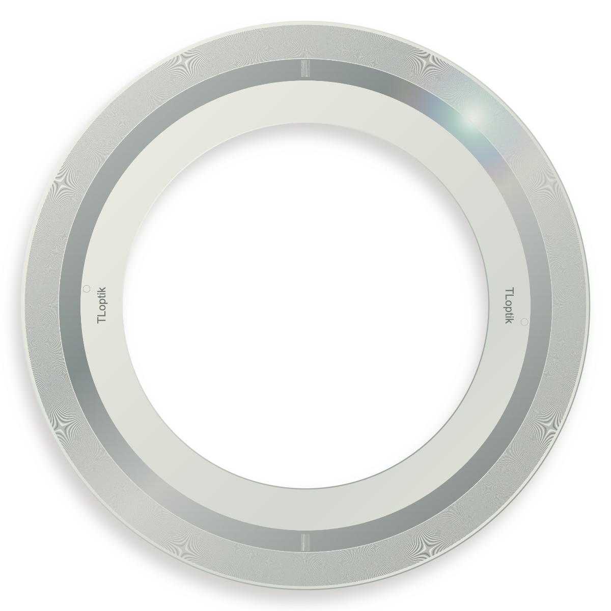
Fine-pattern disc example with an interactive view of the code track.

Periodic angular divisions with a defined index.

Absolute code tracks for compatible angular readout systems.
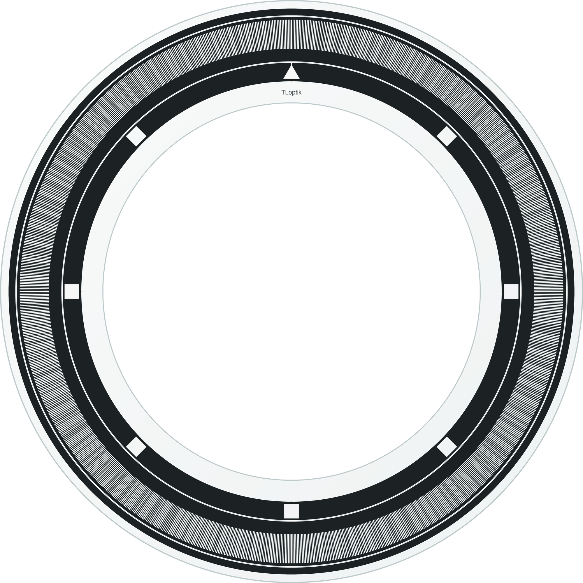
Annular-pattern example for rotary rings and central-clearance layouts.
A circular scale gives a rotary stage a physical angle reference. Large reading radii can provide more distance along a code track for each angular interval, while a central bore leaves space for a bearing, shaft or optical path. The sensor arrangement and installation determine how scale errors appear in the final measurement.
Specify the required angular placement accuracy and track-to-bore concentricity separately from line count. Multiple-readhead systems can compensate for some eccentricity effects, but the pattern, mounting datums and electronics still need a shared error budget.
An indexing table needs repeatable angular locations; a scanning stage also needs useful readout throughout movement. Choose the reference architecture around that task and keep the optical track accessible through the required travel and mechanical arrangement.
Rotary stages use glass encoder discs or rings coupled to the axis as angular references.
Reading radius, centring and readhead placement influence installed performance. Specify component geometry separately from full-system angular accuracy.
The same angle spans a longer arc at a larger radius, changing feature geometry and installation space. Radius alone does not determine system accuracy.