Servo and motion feedback
The readhead samples periodic tracks while the controller accumulates direction and displacement. Index timing relates the counted position to the machine reference.
Convert optical periods into counts and speed limits
An incremental encoder disc carries periodic optical tracks that a readhead converts into motion signals. It supports angular displacement and speed feedback, with an index track available for a defined reference position.
Choose it when the controller counts motion from a reference and the machine can establish that reference at startup. The periodic track and index layout must match the reader.
A periodic track measures movement; an absolute code identifies position within its encoded range. An index identifies a reference location, while A/B phase lets the electronics determine direction.
Optical period count, active track radii, clear/opaque widths, index geometry, mounting bore and zero datum can be coordinated with the readhead layout.
A patterned glass disc with the selected track layout, mounting geometry and component inspection records. The light source, readhead, decoder and shaft assembly are defined by the instrument design.
| Substrate | B270 / K9 / soda-lime glass; fused silica by request |
|---|---|
| Pattern medium | Chromium-on-glass or a specified clear/opaque pattern |
| Photolithographic line-width tolerance | ±0.2 µm |
| Mechanical cutting accuracy | ±0.02 mm |
| Thickness | ≥0.4 mm |
| Total thickness variation (TTV) | ≤2 µm |
| Surface figure | λ/4 |
| Optical mode | Transmissive or reflective, matched to the readhead wavelength |
| Maximum disc diameter | 1500 mm |
| Pattern-to-bore concentricity | ≤0.02 mm |
A disc or scale is the passive optical reference inside a larger encoder system. The artwork, readhead and mounting datum must be designed together so that the manufactured pattern is read in the intended direction and at the intended contrast.
| Property | Specification |
|---|---|
| Pattern architecture | Repeated radial tracks with an optional index (Z) track |
| Signal definition | Optical periods, pulses per revolution or decoded counts, as stated on the drawing |
| Critical geometry | Line count, angular pitch, duty cycle, track radius and index datum |
| Readhead interface | Sensor wavelength, gap, spot size and clear/opaque contrast |
System resolution and system accuracy are separate from the manufactured CD and outline values. Interpolation, bearing runout, eccentricity, alignment and electronics contribute to the final error budget.
Photolithography-patterned glass discs with repeating radial tracks for incremental angular position, speed feedback and motion control. Define A/B quadrature tracks, an index (Z) track, line count and track radius to match the readhead.

The readhead samples periodic tracks while the controller accumulates direction and displacement. Index timing relates the counted position to the machine reference.
Convert optical periods into counts and speed limitsTrack placement, reading radius and pattern-to-shaft centring matter in rotary tables, surveying axes and inspection instruments.
Estimate mounting eccentricity at the reading radiusCheck angular pitch, line width, duty cycle, index position and code-track concentricity relative to the bore. Where required, verify A/B phase geometry, zero-angle registration and accumulated angular error across the active track.
| Property | Specification |
|---|---|
| Pattern dimensions | Measured CD at agreed locations; report nominal and measured values |
| Outline geometry | Outer diameter, bore or scale length checked to the mechanical drawing |
| Registration | Pattern origin, track-to-bore or pattern-to-datum position |
| Optical defects | Clear/opaque defects, broken lines, pinholes and contamination |
| Traceability | Drawing revision, lot identification, inspection method and report |
| Property | Specification |
|---|---|
| Geometry | Disc outer diameter and bore, or scale length, width and thickness |
| Pattern data | Approved artwork or code map, line count/pitch, polarity and revision |
| Optical interface | Transmissive or reflective mode, wavelength, contrast and readhead gap |
| Datum scheme | Mechanical datum, pattern origin, index/zero position and orientation |
| Acceptance record | CD measurement, cutting dimensions, registration, defects and report format |
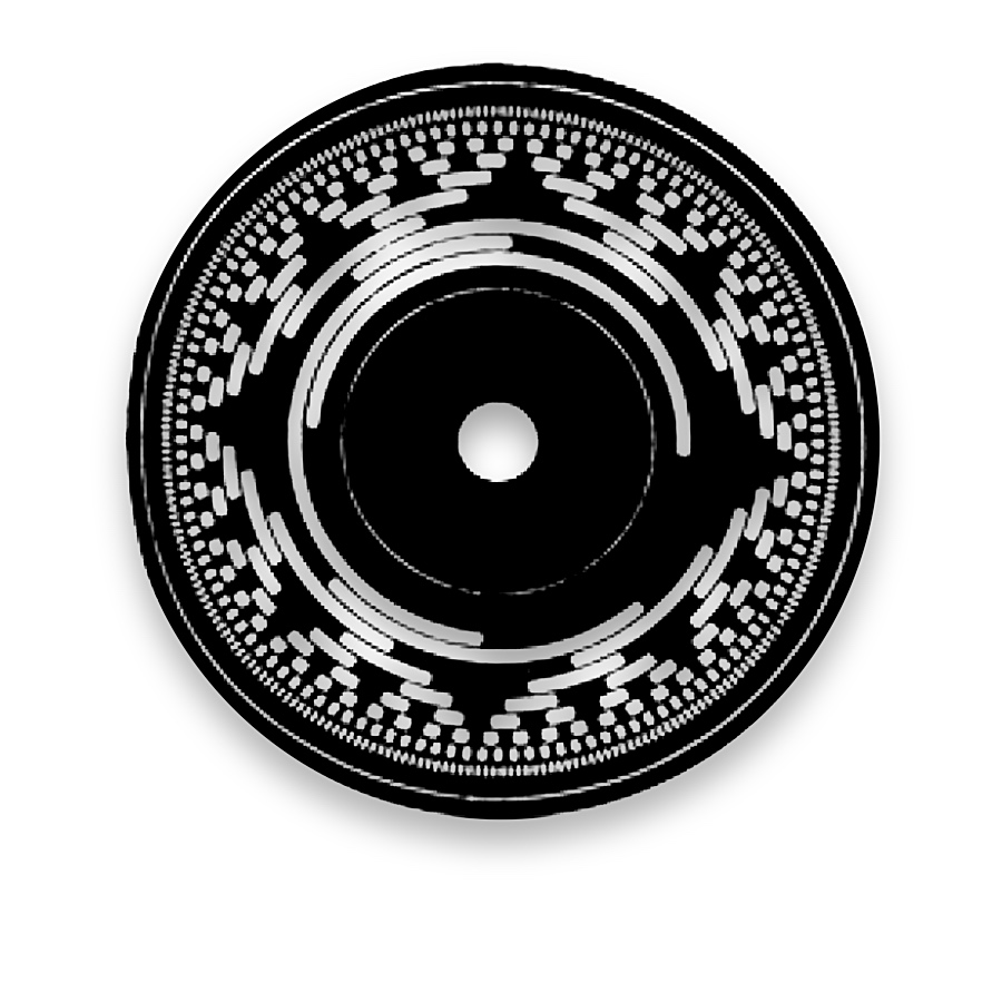
Specify substrate material and geometry together with the operating wavelength. For transmissive reading, define clear-area transmission and opaque-track density. Reflective reading also needs the high/low reflectance pair and illumination geometry. Optical contrast must match the readhead, not only the appearance of the part.
Compare transmissive and reflective readoutQuality & Inspection PhotolithographyPeriodic tracks for relative angular movement and index referencing.
Relative motor or joint rotation with a specified reference track.
Periodic code tracks for angular increments and speed-derived measurements.
Periodic angular divisions with a defined index.
Periodic angular reference for instruments with a compatible reference strategy.
Not in every architecture. Some readers generate phase-shifted channels from one periodic track using offset sensing fields; others use distinct tracks. The reader layout determines the artwork.
Incremental encoder discs provide repeating radial light-and-dark tracks for relative angle and speed sensing.
Separate optical periods per revolution, A/B phase arrangement and the Z index. State optical line count independently of electronically multiplied counts.
Period count, reading radius, duty cycle, index geometry and angle, bore and readhead layout.
Controller multiplication and interpolation determine reported counts. State the optical period count on the drawing and the electronic counting convention in the system specification.