Reference recovery
A single reference mark establishes a defined coordinate. Distance-coded reference patterns need the corresponding reader and homing logic.
Calculate linear increments from pitch and subdivision
An incremental linear scale repeats optical graduations along an axis. The readhead measures changes in position from that periodic reference; separate reference marks can establish a machine coordinate.
Choose it when the machine can establish an axis reference and the reader is compatible with the physical pitch, track arrangement and optical contrast.
The manufactured pitch is a physical period. The reported increment depends on how the readhead and electronics subdivide it; a finer displayed increment is not a full-travel accuracy value.
Grating pitch, clear/opaque ratio, measuring length, track widths, reference-mark arrangement and mounting datum can be defined independently.
A patterned glass scale with the selected measuring length, code or grating layout, reference marks and component inspection records.
| Substrate | B270 / K9 / soda-lime glass; fused silica by request |
|---|---|
| Pattern medium | Chromium-on-glass or a specified clear/opaque pattern |
| Photolithographic line-width tolerance | ±0.2 µm |
| Mechanical cutting accuracy | ±0.02 mm |
| Thickness | ≥0.4 mm |
| Total thickness variation (TTV) | ≤2 µm |
| Surface figure | λ/4 |
| Optical mode | Transmissive or reflective, matched to the readhead wavelength |
| Active scale length | Defined by the approved drawing |
| Reference-mark position | Defined from the mounting datum |
A disc or scale is the passive optical reference inside a larger encoder system. The artwork, readhead and mounting datum must be designed together so that the manufactured pattern is read in the intended direction and at the intended contrast.
| Property | Specification |
|---|---|
| Pattern architecture | Periodic chrome lines with optional reference marks |
| Signal definition | Manufactured pitch is specified separately from interpolated electrical resolution |
| Critical geometry | Pitch, duty cycle, active length, line direction and reference-mark datum |
| Readhead interface | Wavelength, sensing gap, aperture and contrast matched to the readhead |
System resolution and system accuracy are separate from the manufactured CD and outline values. Interpolation, bearing runout, eccentricity, alignment and electronics contribute to the final error budget.
Periodic chrome-on-glass linear scales for displacement sensing, with reference marks and track geometry matched to the readhead.
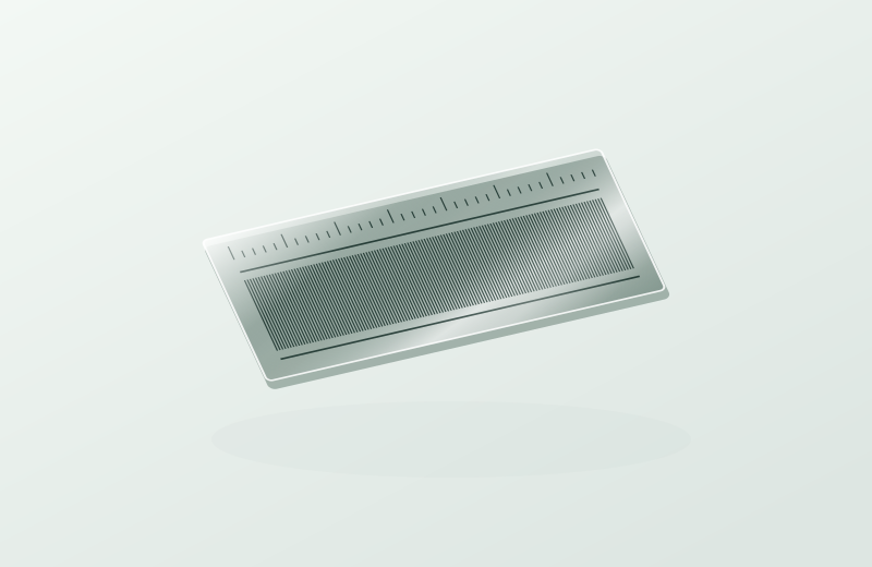
A single reference mark establishes a defined coordinate. Distance-coded reference patterns need the corresponding reader and homing logic.
Calculate linear increments from pitch and subdivisionLocal line-width measurements and errors between positions over the measuring length answer different inspection questions.
Inspect pitch and accumulated intervalsCheck pitch and accumulated interval error over specified lengths, reference-mark position and line defects.
| Property | Specification |
|---|---|
| Pattern dimensions | Measured CD at agreed locations; report nominal and measured values |
| Outline geometry | Outer diameter, bore or scale length checked to the mechanical drawing |
| Registration | Pattern origin, track-to-bore or pattern-to-datum position |
| Optical defects | Clear/opaque defects, broken lines, pinholes and contamination |
| Traceability | Drawing revision, lot identification, inspection method and report |
| Property | Specification |
|---|---|
| Geometry | Disc outer diameter and bore, or scale length, width and thickness |
| Pattern data | Approved artwork or code map, line count/pitch, polarity and revision |
| Optical interface | Transmissive or reflective mode, wavelength, contrast and readhead gap |
| Datum scheme | Mechanical datum, pattern origin, index/zero position and orientation |
| Acceptance record | CD measurement, cutting dimensions, registration, defects and report format |
Specify substrate material and geometry together with the operating wavelength. For transmissive reading, define clear-area transmission and opaque-track density. Reflective reading also needs the high/low reflectance pair and illumination geometry. Optical contrast must match the readhead, not only the appearance of the part.
Compare glass scale readout and encoding optionsQuality & Inspection PhotolithographyPeriodic scale tracks with reference marks for homing.
Incremental linear scales use periodic lines to provide an optical reference for relative linear displacement.
Pitch, transparent-to-opaque duty cycle, active length and reference marks define the pattern. Head optics and interpolation determine system output.
Pitch, active length, reference marks, track width, substrate and readhead gap.
Pitch is the pattern repeat distance. Electrical resolution also depends on phase reading, multiplication and interpolation settings.