Clear and opaque contrast
Clear-region transmission and blocked-region leakage are evaluated at the reader wavelength. Visible darkness alone does not specify the detector signal.
Match illumination, pattern face and sensing fields
A transmissive glass scale places transparent and opaque features in the light path between a source and detector. Its repeating or coded pattern provides the optical reference for linear position sensing.
Choose it when the assembly provides optical access to both sides of the scale and the readhead uses transmitted light.
Transmission defines the light path; incremental and absolute define position encoding. A reflective reader uses returned light from one side and needs a different optical contrast specification.
Pitch or code sequence, active measuring length, track width, reference marks, film side and mounting datums can be coordinated with the sensing window.
A patterned glass scale with the selected measuring length, code or grating layout, reference marks and component inspection records.
| Substrate | B270 / K9 / soda-lime glass; fused silica by request |
|---|---|
| Pattern medium | Chromium-on-glass or a specified clear/opaque pattern |
| Photolithographic line-width tolerance | ±0.2 µm |
| Mechanical cutting accuracy | ±0.02 mm |
| Thickness | ≥0.4 mm |
| Total thickness variation (TTV) | ≤2 µm |
| Surface figure | λ/4 |
| Optical mode | Transmissive; source and detector on opposite sides |
| Active scale length | Defined by the approved drawing |
| Reference-mark position | Defined from the mounting datum |
A disc or scale is the passive optical reference inside a larger encoder system. The artwork, readhead and mounting datum must be designed together so that the manufactured pattern is read in the intended direction and at the intended contrast.
| Property | Specification |
|---|---|
| Position encoding | Incremental grating or approved absolute code sequence |
| Optical acceptance | Clear-area transmission and opaque-area OD at the operating wavelength |
| Critical geometry | Pitch, duty cycle, active length, track width and pattern-to-datum position |
| Readhead interface | Patterned face, sensing window, reading direction and operating gap |
System resolution and system accuracy are separate from the manufactured CD and outline values. Interpolation, bearing runout, eccentricity, alignment and electronics contribute to the final error budget.
Custom chrome-on-glass linear encoder scales for transmitted-light readheads. Clear and opaque tracks define the optical signal; incremental gratings or absolute code sequences are manufactured to your approved artwork.
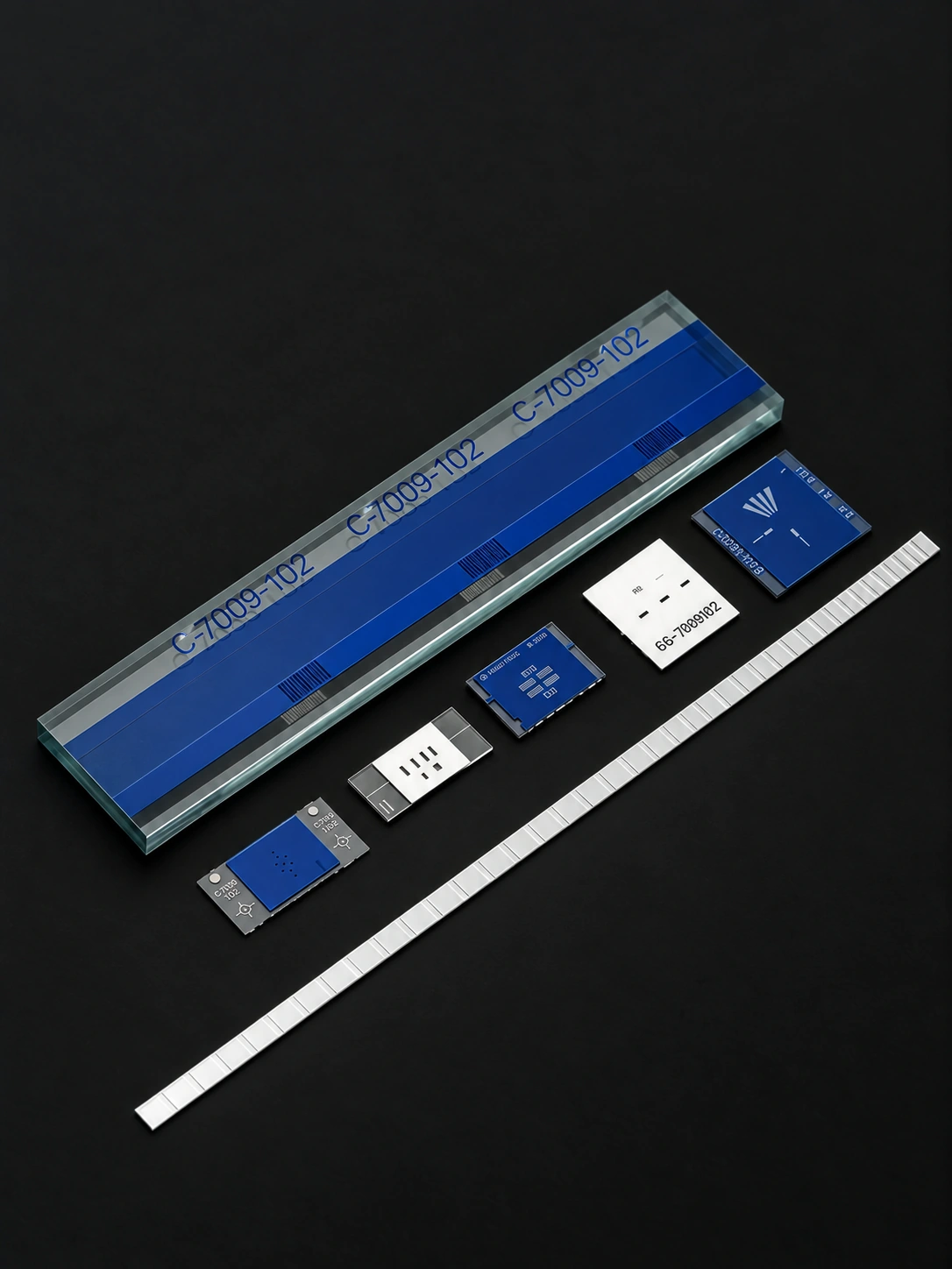
Clear-region transmission and blocked-region leakage are evaluated at the reader wavelength. Visible darkness alone does not specify the detector signal.
Match illumination, pattern face and sensing fieldsThe patterned face, glass thickness and sensing gap determine where the reader observes the grating. Rear-surface reflections can contribute stray light.
Relate grating pitch to linear output incrementsInspect line width and spacing, pitch error over agreed intervals, reference-mark position, pinholes in opaque regions and residues in clear spaces. Record clear-area transmission and opaque-area OD at the specified wavelength. State whether measurements refer to the free scale or its mounted condition and record the reference temperature for length measurements.
| Property | Specification |
|---|---|
| Pattern dimensions | Measured CD at agreed locations; report nominal and measured values |
| Outline geometry | Outer diameter, bore or scale length checked to the mechanical drawing |
| Registration | Pattern origin, track-to-bore or pattern-to-datum position |
| Optical defects | Clear/opaque defects, broken lines, pinholes and contamination |
| Traceability | Drawing revision, lot identification, inspection method and report |
| Property | Specification |
|---|---|
| Geometry | Disc outer diameter and bore, or scale length, width and thickness |
| Pattern data | Approved artwork or code map, line count/pitch, polarity and revision |
| Optical interface | Transmissive or reflective mode, wavelength, contrast and readhead gap |
| Datum scheme | Mechanical datum, pattern origin, index/zero position and orientation |
| Acceptance record | CD measurement, cutting dimensions, registration, defects and report format |
Specify substrate material and geometry together with the operating wavelength. For transmissive reading, define clear-area transmission and opaque-track density. Reflective reading also needs the high/low reflectance pair and illumination geometry. Optical contrast must match the readhead, not only the appearance of the part.
Compare glass scale readout and encoding optionsQuality & Inspection PhotolithographyGlass scales for a readhead with optical access to both sides.
Transmissive glass scales modulate light passing through clear and opaque regions for position reading.
The emitter and detector are on opposite sides. Define pattern polarity, film side and the space needed for the transmitted optical path.
Pitch or code, wavelength, transmission and opacity, active length, viewing side and head gap.
Their illumination, detector placement and contrast mechanisms differ. Match the readhead and film stack when changing optical mode.