
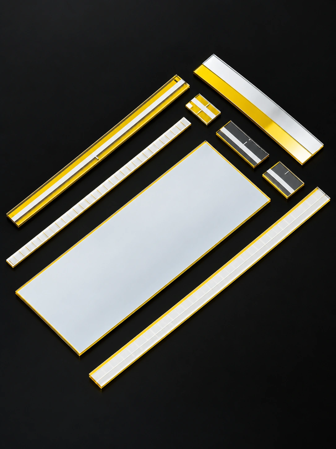
Reflective Glass Encoder Scales

Position feedback from one side of the scale.

Patterned glass encoder componentCustom formats

Product selection

What it is and what it does

A reflective glass scale presents high- and low-reflectance regions to a source and detector on the same side. The matching readhead uses the changing reflected intensity to read position.

When to choose it

Choose it when the reader is designed for one-sided optical access and its wavelength, illumination angle and sensing window match the coating and pattern.

How it differs from related products

Reflective and transmissive are optical geometries, not encoding methods. Both can use a periodic grating or an absolute code when paired with a suitable reader.

What can be customised

High/low reflectance, track layout, active length, reference geometry and the mounting face are defined together with the reader collection geometry.

What you receive

A patterned glass scale with the selected measuring length, code or grating layout, reference marks and component inspection records.

Specifications and inspection

Product configuration

Reflective Glass Encoder Scales
SubstrateB270 / K9 / soda-lime glass; fused silica by request
Pattern mediumChromium-on-glass or a specified clear/opaque pattern
Photolithographic line-width tolerance±0.2 µm
Mechanical cutting accuracy±0.02 mm
Thickness≥0.4 mm
Total thickness variation (TTV)≤2 µm
Surface figureλ/4
Optical modeReflective; source and detector on the same side
Active scale lengthDefined by the approved drawing
Reference-mark positionDefined from the mounting datum

Pattern architecture and system fit

A disc or scale is the passive optical reference inside a larger encoder system. The artwork, readhead and mounting datum must be designed together so that the manufactured pattern is read in the intended direction and at the intended contrast.

Pattern and readhead interface
PropertySpecification
Position encodingIncremental grating or approved absolute code sequence
Optical acceptanceHigh/low reflectance at the specified wavelength and incidence angle
Critical geometryPitch, duty cycle, active length, track width and pattern-to-datum position
Readhead interfacePatterned face, sensing window, reading direction and operating gap

System resolution and system accuracy are separate from the manufactured CD and outline values. Interpolation, bearing runout, eccentricity, alignment and electronics contribute to the final error budget.

Custom reflective glass scales for optical linear encoders with the source and detector on the same side. High- and low-reflectance pattern regions are specified together with the readhead wavelength, angle and sensing gap.

Built for your process.

Request a Quote
Reflective Glass Encoder Scales

Read position from one side

Collected contrast

Specify both reflectance levels at the intended wavelength and angle. The detector receives light through its aperture, so surface reflectance and usable signal contrast are related but distinct quantities.

Understand how optics and coating shape the signal

Background reflections

Transparent areas can expose a rear surface or mounting background. Those reflections must be included when evaluating the installed signal.

Relate scale pitch to output resolution

Inspection and acceptance

Inspect pattern dimensions, cumulative interval error and registration to the mounting datum. Measure both bright and dark reflectance under the agreed optical geometry, and examine scratches, contamination and coating defects in the read zone. Readhead signal validation belongs to the assembled system and should use the intended mounting gap and illumination.

Inspection record
PropertySpecification
Pattern dimensionsMeasured CD at agreed locations; report nominal and measured values
Outline geometryOuter diameter, bore or scale length checked to the mechanical drawing
RegistrationPattern origin, track-to-bore or pattern-to-datum position
Optical defectsClear/opaque defects, broken lines, pinholes and contamination
TraceabilityDrawing revision, lot identification, inspection method and report
Specify high and low reflectance separately

What to include in the drawing

Drawing and inquiry checklist
PropertySpecification
GeometryDisc outer diameter and bore, or scale length, width and thickness
Pattern dataApproved artwork or code map, line count/pitch, polarity and revision
Optical interfaceTransmissive or reflective mode, wavelength, contrast and readhead gap
Datum schemeMechanical datum, pattern origin, index/zero position and orientation
Acceptance recordCD measurement, cutting dimensions, registration, defects and report format

Substrate & optical configuration

Specify substrate material and geometry together with the operating wavelength. For transmissive reading, define clear-area transmission and opaque-track density. Reflective reading also needs the high/low reflectance pair and illumination geometry. Optical contrast must match the readhead, not only the appearance of the part.

Compare glass scale readout and encoding optionsQuality & Inspection Photolithography

Where this product is used

Selection notes

Reflective glass scales use surface reflectance differences to provide a position pattern to a head on the same side.

Specify wavelength, incidence angle, reading face and window together with the required contrast, then define pitch or code and datums.

Information for your inquiry

Wavelength, incidence angle, reflective contrast, film side, pitch or coding and mounting margins.

Why specify incidence angle for a reflective scale?

The light received by the head depends on the optical arrangement. Angle and reading side connect the film requirement to the actual detector geometry.

Search