What the component does
A code disc supplies the angular reference. A central opening can leave room for shafts, cabling or other joint hardware.

Locate a robot joint within its motion range by reading a code pattern coupled to the chosen measurement shaft.
The sketch shows an output-axis arrangement. Motor-side sensing and output-side sensing observe different parts of a geared joint.
The decoder interprets the pattern, and the controller relates that reading to the joint coordinate system.
A code disc supplies the angular reference. A central opening can leave room for shafts, cabling or other joint hardware.
Choose motor-side or output-side measurement intentionally. Gear ratio, backlash and elastic deflection affect how one reading relates to the other.
A Gray-code pattern requires compatible track sampling and decoding. A mismatch can produce incorrect position words rather than merely a small offset.

Absolute angular coding with one-bit changes between adjacent ideal code positions.

Relative motor or joint rotation with a specified reference track.
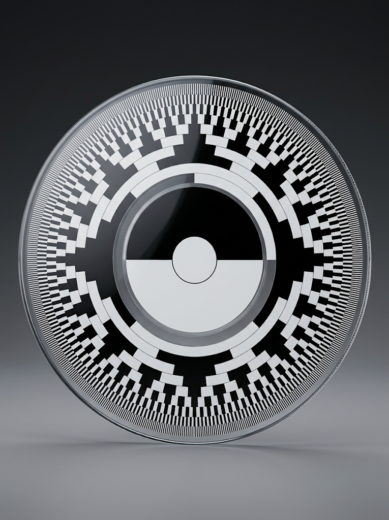
Natural-binary patterns for readheads and decoders designed for that code.
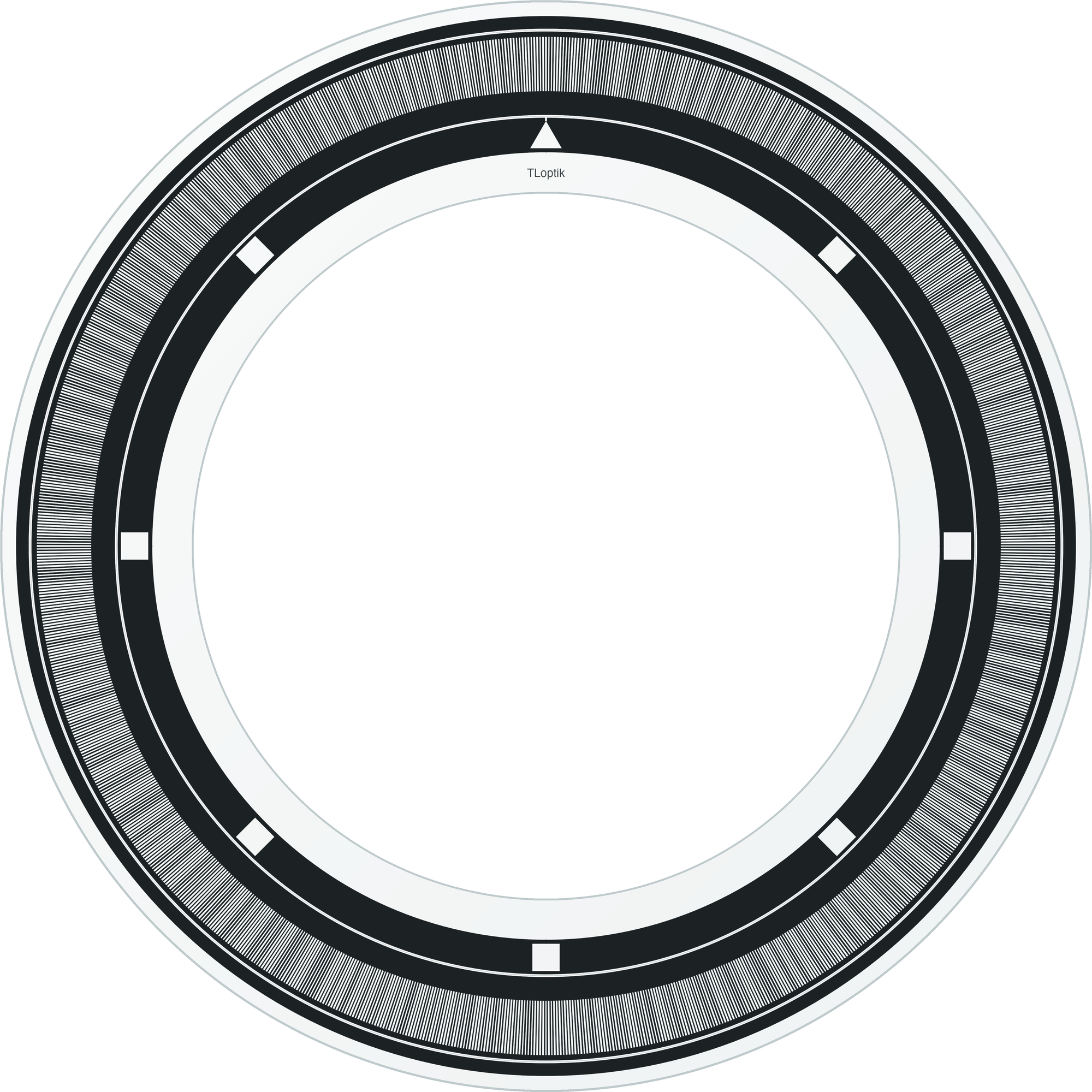
An annular design example for discussing ring geometry and track placement.
Joint feedback may be measured at the motor shaft, the gearbox output or both. A motor-side encoder measures motor motion, while an output-side encoder can observe joint movement after the transmission. The mounting location changes the required disc diameter, bore and relationship between code tracks and mechanical datums.
Absolute patterns can identify position within the encoded range without an index search when supported by the readhead. A single-turn disc does not alone retain a multi-turn count. For hollow joints, a ring-shaped disc can accommodate a central passage, subject to stiffness, support and mounting constraints.
Joint position at startup influences how a robot can resume a task. Absolute and incremental feedback impose different referencing sequences. Hollow-shaft clearance, flexing mounts and contamination protection should be considered with the readhead layout.
Robot joint feedback uses an encoder pattern coupled to the measured axis as an angle reference.
Choose the feedback location first: motor-shaft motion and reducer-output motion are different. Then define the code tracks and installation.
A single-turn optical pattern identifies positions within its encoded range. Multi-turn information needs a corresponding system mechanism or counting strategy.