What the component does
The disc encodes rotation about its own axis. A telescope crosshair supplies a pointing reference, but does not replace angle encoding.

Provide separate angular references for the horizontal and vertical axes of an optical angle-reading surveying instrument.
The disc follows the rotating structure. Its pattern passes the readhead to provide the horizontal angular reference.
A separate disc and readhead measure telescope elevation. The electronic distance measurement system is a separate functional chain.
The disc encodes rotation about its own axis. A telescope crosshair supplies a pointing reference, but does not replace angle encoding.
Incremental divisions need an established reference. Absolute tracks identify coded positions; Gray coding is one compatible absolute-code approach.
Disc eccentricity, bearing motion and readhead alignment affect the complete instrument. More pattern divisions alone do not establish angular accuracy.

Periodic angular reference for instruments with a compatible reference strategy.

Compare absolute code architectures for direct angular identification.

Parallel Gray-code tracks for a matching angular readhead.
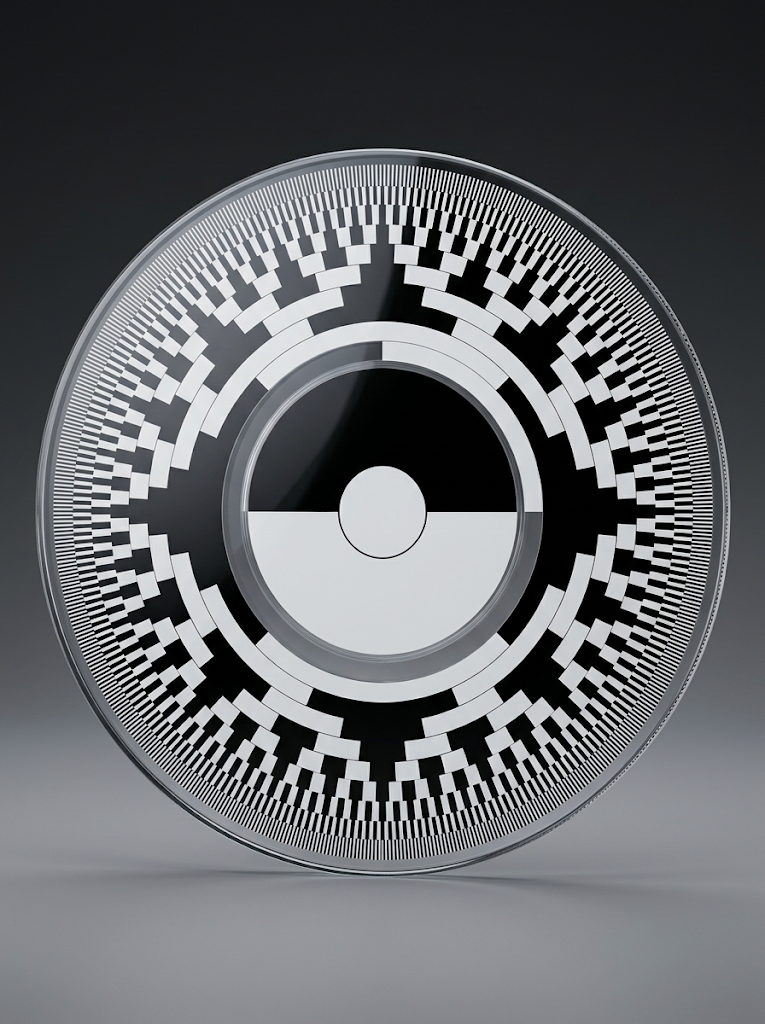
Natural-binary track layouts for compatible decoders.
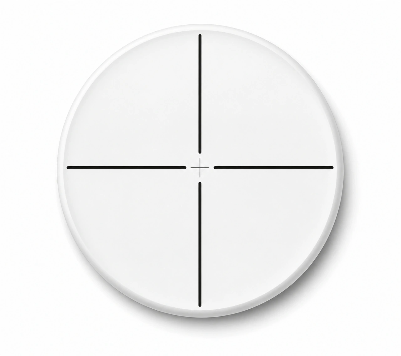
Visible pointing reference in a compatible telescope focal plane.
A surveying instrument relates a line of sight to measured horizontal and vertical angles. In an optical angle-reading architecture, a patterned disc or ring moves relative to a readhead so the system can determine axis rotation. A telescope reticle supplies a separate visible reference for pointing at the target.
Choose the disc pattern around the actual readhead, available radius and startup reference method. Absolute coding can identify an angular interval directly; incremental divisions need an established reference. The reticle pattern and its focal-plane position are chosen around the telescope optics.
Horizontal and vertical angle sensing must each relate the optical pattern to a mechanical axis and a zero convention. The shape of the disc, central clearance and track location follow the instrument structure. A design for a motor encoder is not automatically suitable for a surveying axis.
Pattern placement, disc eccentricity, bearing motion, readhead alignment and temperature can contribute to the complete measurement. Some instruments use multiple reading positions to manage selected errors. Component geometry and whole-instrument angle accuracy should therefore be evaluated separately.
Crosshairs help the operator establish a repeatable sighting reference, while the encoder reports the rotation of the instrument axis. Both functions matter, but the reticle does not replace angle encoding and the code disc does not establish the telescope sight line by itself.
Surveying instruments use encoder discs as angle references for rotating axes and reticles as visible aiming references inside the telescope.
Relate the encoder to the mechanical axis and the reticle to the line of sight; the two components perform different jobs.
No. A reticle supports observation and aiming. An encoder pattern is read by a head to determine axis position.