Field shape
A grid makes straightness, local stretching and axis alignment visible across the image.

Orthogonal grid patterns provide references for image scale, alignment and distortion evaluation. Grid pitch, line width and usable area define the target geometry.
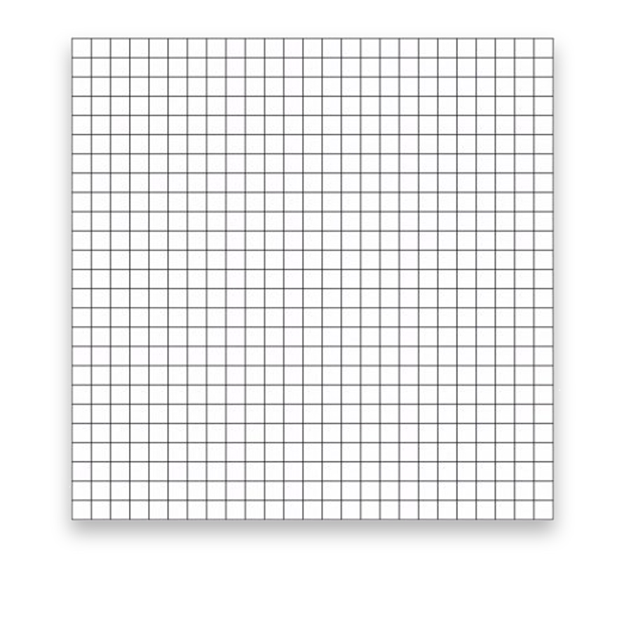
A grid target places known line intersections or square boundaries across an image field. It helps reveal geometric distortion, orientation and spacing differences while providing coordinates for a compatible calibration workflow.
Choose a grid to divide an observation field into known regions, compare spacing or support image-coordinate measurements. Use a counting chamber instead when a liquid volume must be defined.
A grid makes straightness, local stretching and axis alignment visible across the image.
Known intersections can support geometric checks when the detector and measurement model explicitly use them.
| Choice | Selection basis |
|---|---|
| Pitch and line width | Choose pitch for field coverage and line width for clear intersection detection at the working scale. |
| Axis geometry | Define the origin, measured spans and X/Y orthogonality needed for the measurement. |
| Target plane | Keep the reference in the intended object plane. Perspective, lens distortion and target bow can each affect the image. |
Distributed intersections for image scale and distortion mapping.
Measure line spacing, intersection coordinates, orthogonality and the drawing-defined flatness area.
The selected grid is supplied on glass with the defined pitch, line width, reference axes and active area. Any measured coordinates are distinguished from the nominal artwork.
Grid calibration targets provide known lines and intersections for image-scale, alignment and distortion checks.
Define X/Y pitch, origin, line width and field coverage to match the detector and coordinate model.
Pitch, rows and columns, line width, origin, active area, material and imaging conditions.
A line grid supplies line intersections. A checkerboard supplies corners between alternating squares. Choose the visible features and detector together.