What the component does
Checkerboard corners, dot centres and grid intersections provide known coordinates. Choose the geometry that the calibration software can locate reliably.

Relate image coordinates to known target geometry so that a machine vision system can measure position, shape or scale.
The lower dimension shows working distance. The rays illustrate the object field mapped onto the sensor; software uses detected feature coordinates.
For suitable camera models, varied poses and image coverage constrain calibration better than repeated identical views.
Checkerboard corners, dot centres and grid intersections provide known coordinates. Choose the geometry that the calibration software can locate reliably.
Target size, feature spacing and working distance must produce enough well-resolved features across the field. Calibration is tied to the chosen lens and focus state.
Poor flatness or inaccurate feature positions can be interpreted as camera distortion. A resolution target tests image detail and is not a substitute for a geometric calibration pattern.
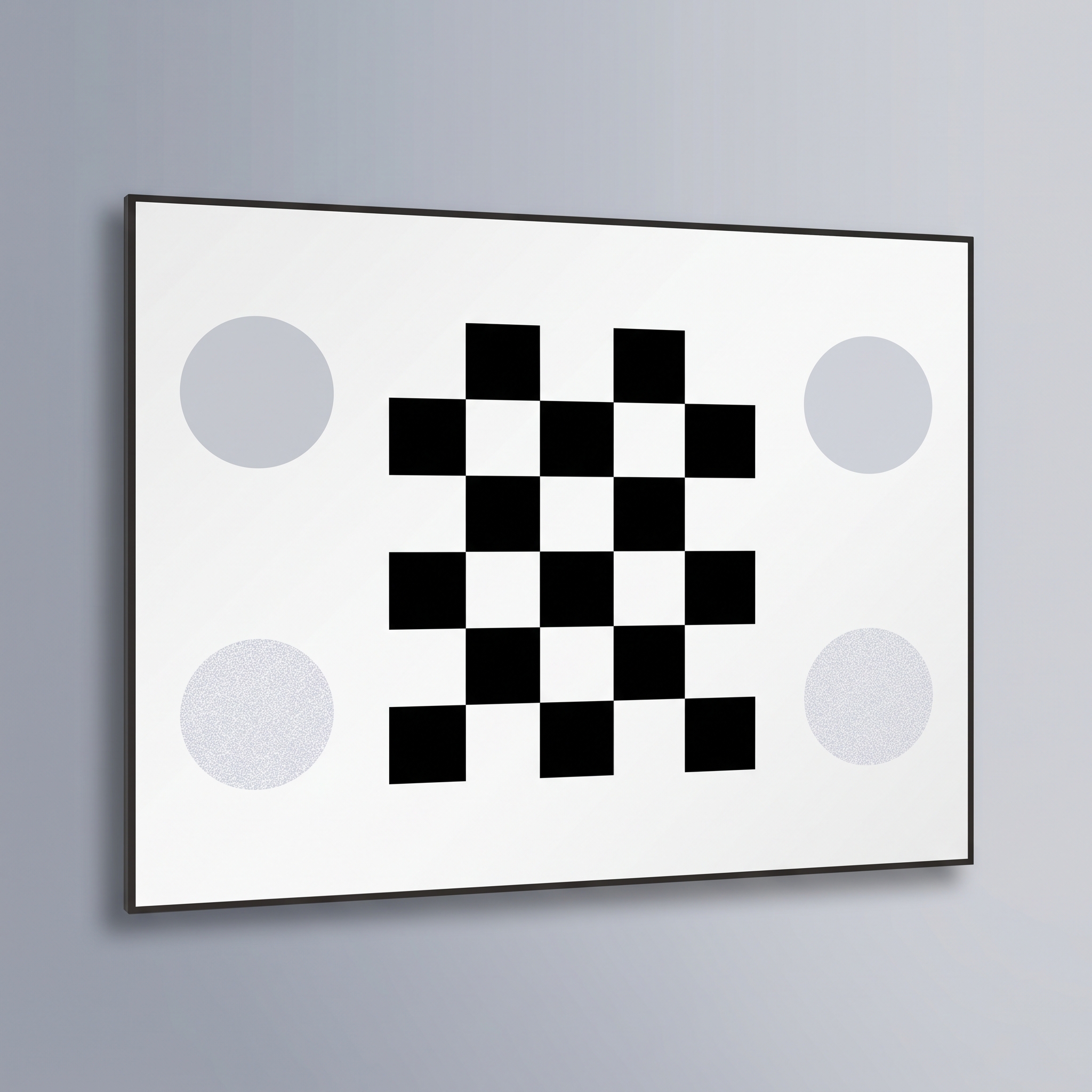
Known internal corners for camera intrinsics, lens-distortion correction and stereo coordinate mapping.
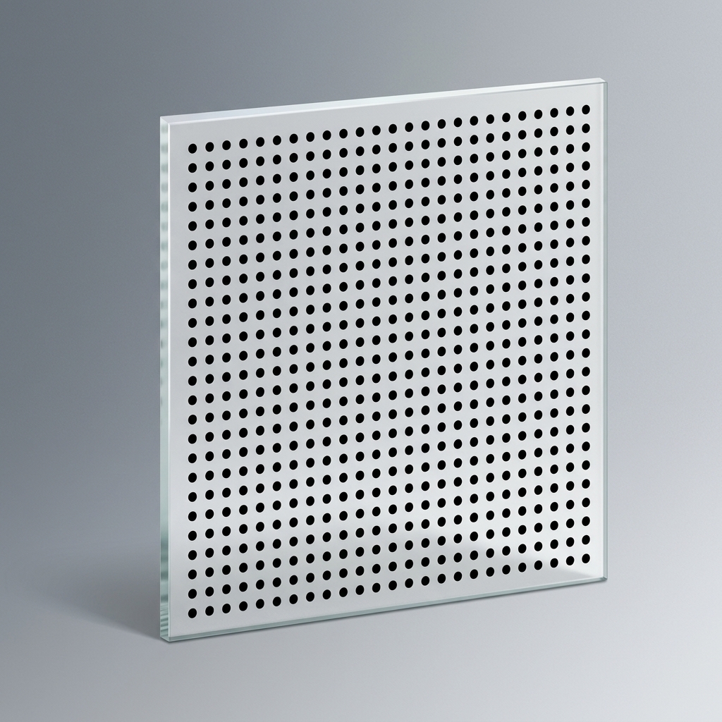
Known circular-feature coordinates for geometric calibration, field mapping and multi-camera correspondence.
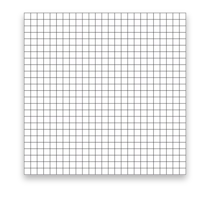
Distributed intersections for image scale and distortion mapping.
Compare geometries for camera intrinsic and distortion calibration.
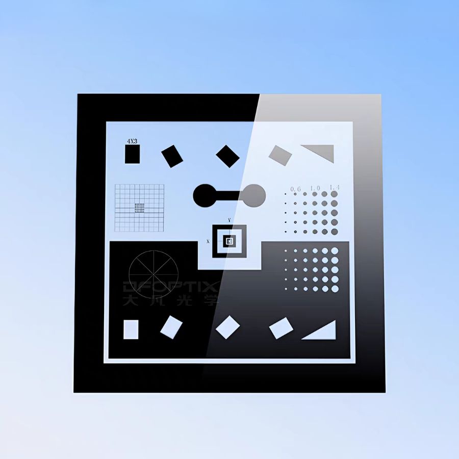
Combine scale, alignment and detail checks in one fixture.
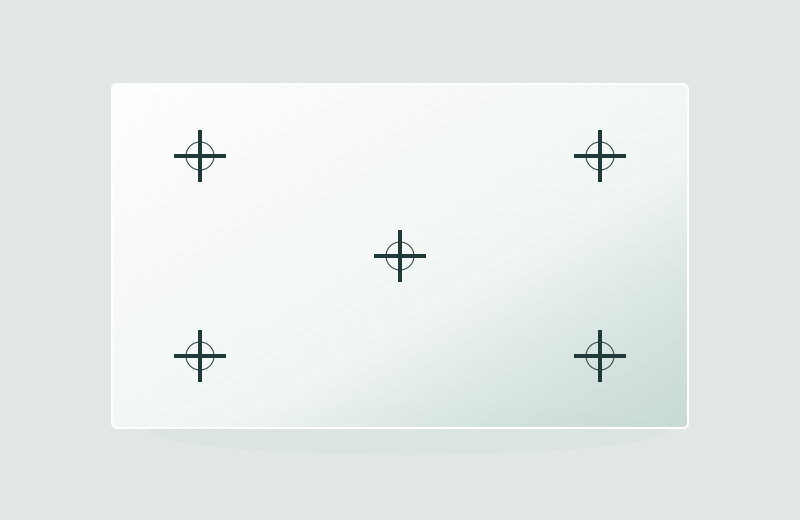
Alignment features for repeat imaging and fixture registration.
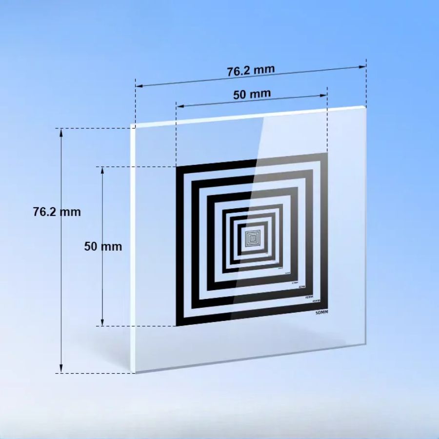
Nested frames show image centring, edge straightness and apparent geometry across the camera field.
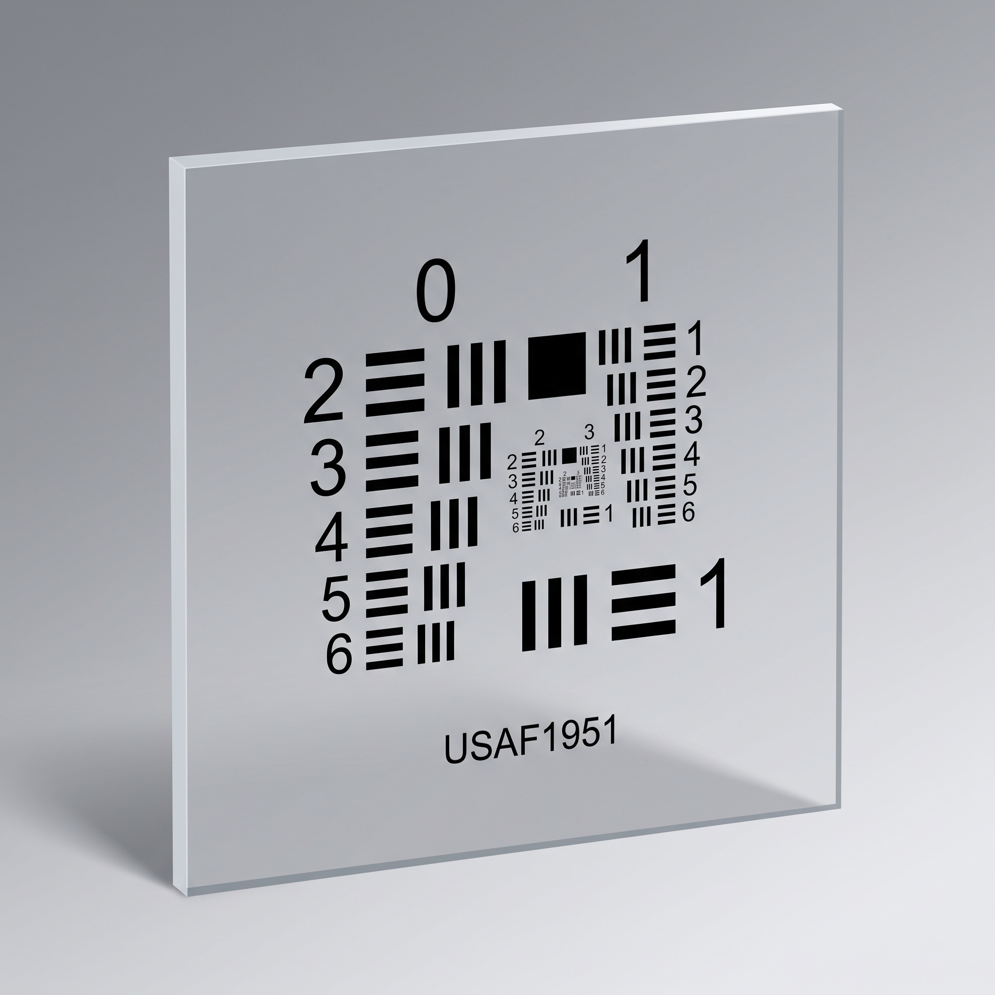
Checks resolved image detail as a separate test after geometric calibration.
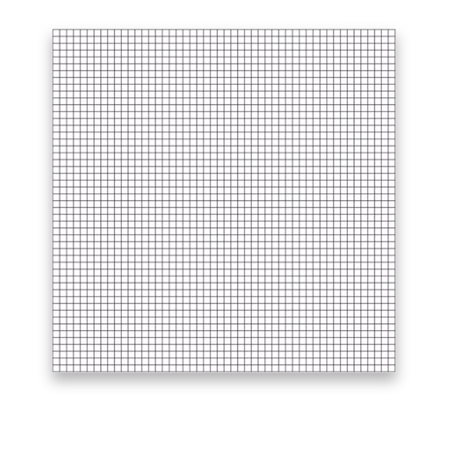
Known feature positions for image scale and geometric calibration.
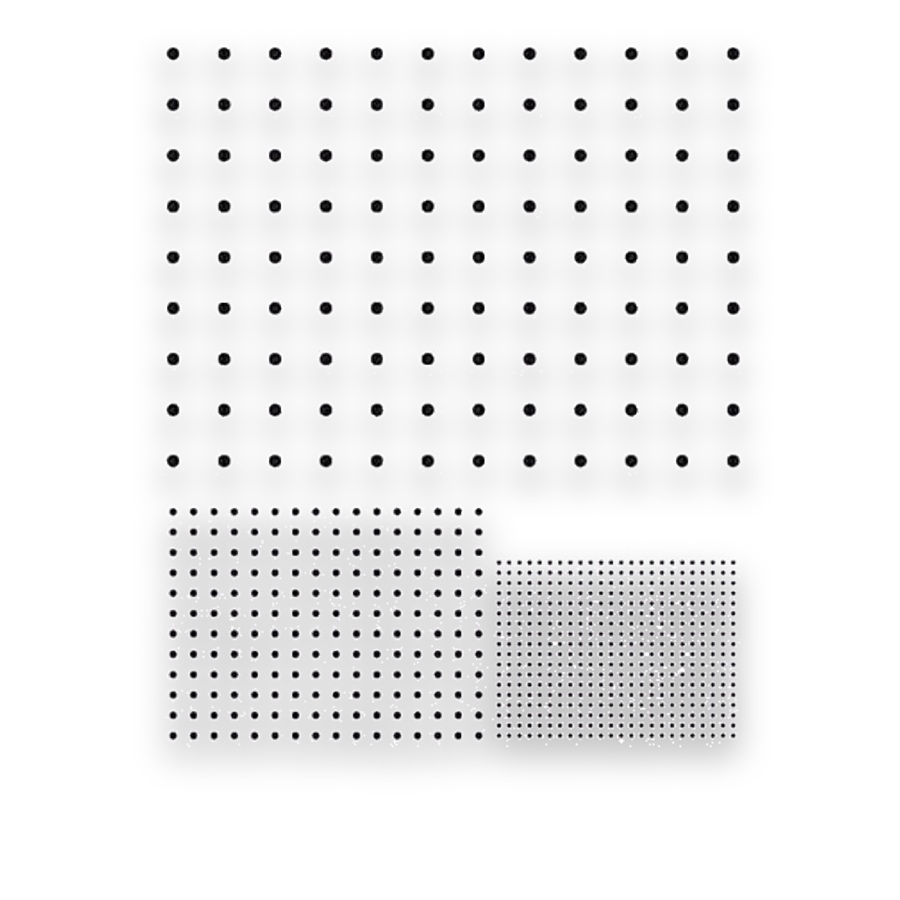
Known feature positions for image scale and geometric calibration.
Known feature positions for image scale and geometric calibration.
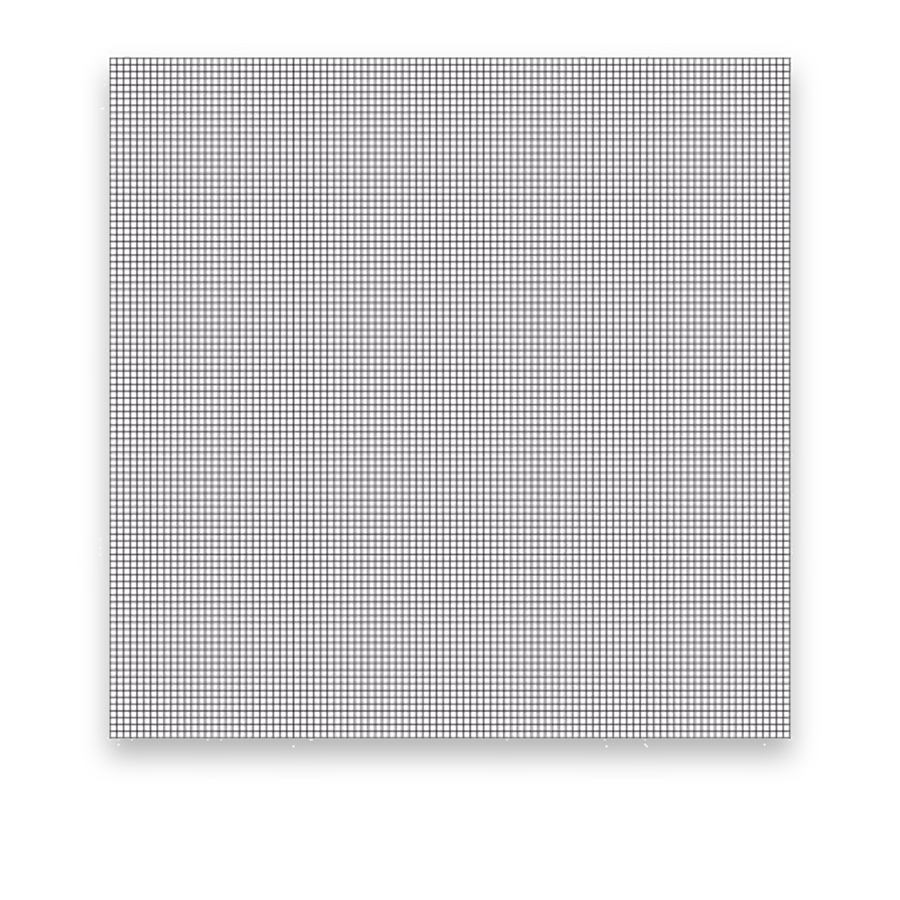
Known feature positions for image scale and geometric calibration.
Known feature positions for image scale and geometric calibration.
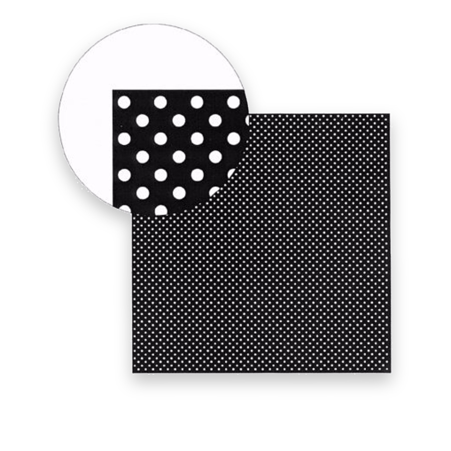
Known feature positions for image scale and geometric calibration.
A camera-based measurement system needs known physical features to relate image coordinates to the object. Calibration patterns help estimate image scale, lens distortion and camera pose; fiducials support alignment between images, fixtures and parts. Choose a pattern that your software can locate reliably.
Match target pitch and active area to the field of view and pixel sampling. Pattern-position errors and substrate flatness enter the measurement uncertainty, so a nominal pitch alone does not define calibration accuracy. Distortion calibration and sharpness evaluation are different tasks.
A camera target can support intrinsic calibration, stereo-camera relationships or a robot vision workflow, depending on the software and captures. A robot hand–eye calibration also requires corresponding robot poses; the target alone does not determine the robot-to-camera transform.
A sharp image may still contain geometric distortion, while a calibrated camera can be out of focus. Combine geometric targets with a suitable resolution check when both dimensional measurement and small-feature visibility matter.
Dot centres and checkerboard corners are alternative coordinate features. Match their count, pitch and ordering to the software, collect views across the usable field and validate independent dimensions after fitting. Use a resolution target separately when the question is whether fine detail can be resolved.
Machine-vision calibration relates known physical target geometry to image coordinates and the measurement model.
Identify whether the task is intrinsic calibration, stereo geometry, hand–eye transformation or image scale before choosing a checkerboard, circles, grid or scale.
It describes fit to the captured observations. Verify real dimensions with independent geometry in the intended working configuration.