Lens and camera comparisons
Compare the last correctly resolved element with the aperture, exposure and processing held constant.

Three-bar USAF 1951 targets for comparing the resolving power of cameras, microscopes and imaging optics. Select the group range, polarity and glass format within one product family.
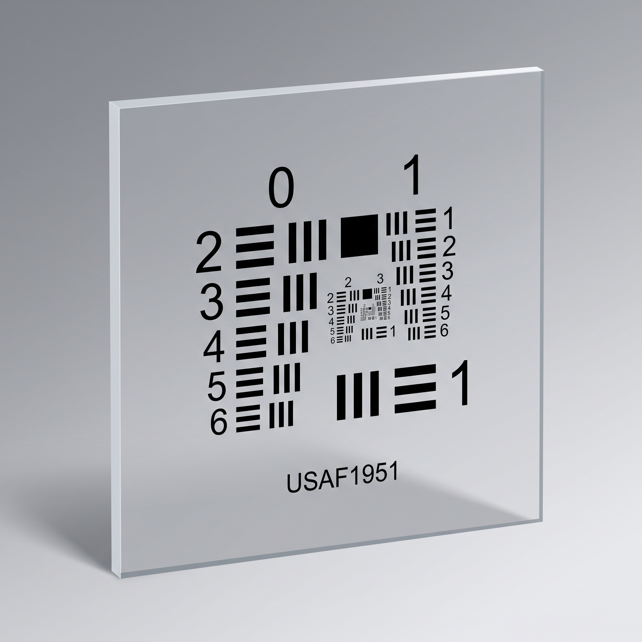
A USAF 1951 target contains labelled groups of three horizontal and three vertical bars. Progressively finer elements provide a recognised reference for the smallest detail an imaging system can reliably separate.
Choose it for a labelled resolution reading, an assembly focus check or a comparison between optical configurations. Record both bar directions at the working distance and magnification used in the test.
Compare the last correctly resolved element with the aperture, exposure and processing held constant.
Check the complete optical path, including the objective, camera adapter and sampling, at the field positions used for inspection.
| Choice | Selection basis |
|---|---|
| Group and element range | Match the finest and coarsest elements to the expected detail and image magnification. The glass outline does not determine resolution. |
| Clear and opaque regions | Select dark bars on a clear field or clear bars in an opaque field for the lighting arrangement. |
| Active field and mounting | Keep the required groups visible within the field of view, with room for the holder outside the test area. |
USAF provides discrete labelled frequencies. A Siemens star compares radial detail in many directions; a slanted edge supports software-based SFR analysis.
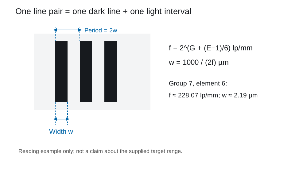
Convert group and element to line width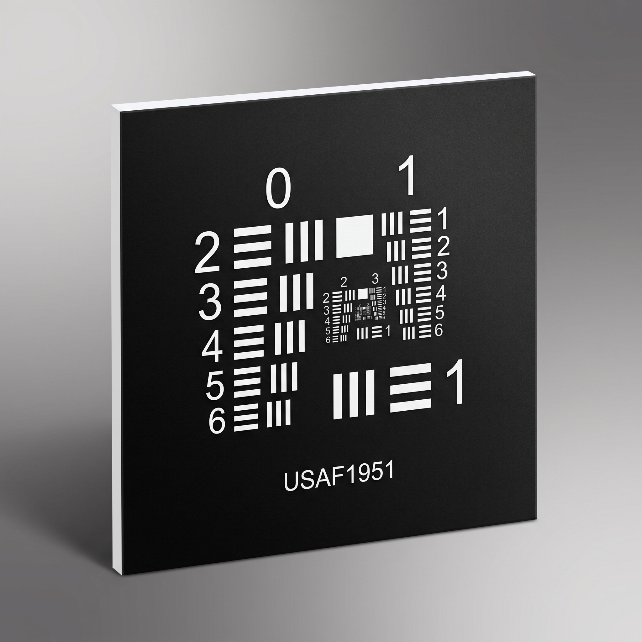
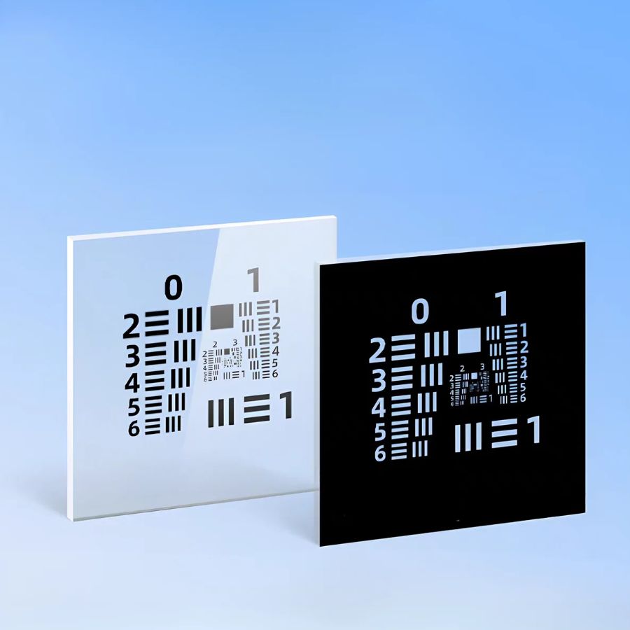
The positive target shown above has dark bars on a light field. This negative version reverses the contrast, showing light bars on a dark field. Both use numbered horizontal and vertical three-bar elements; choose the clear and opaque regions for the intended lighting arrangement.
State the pattern side and required group/element range in the drawing.
76.2 mm format
Horizontal and vertical three-bar groups.
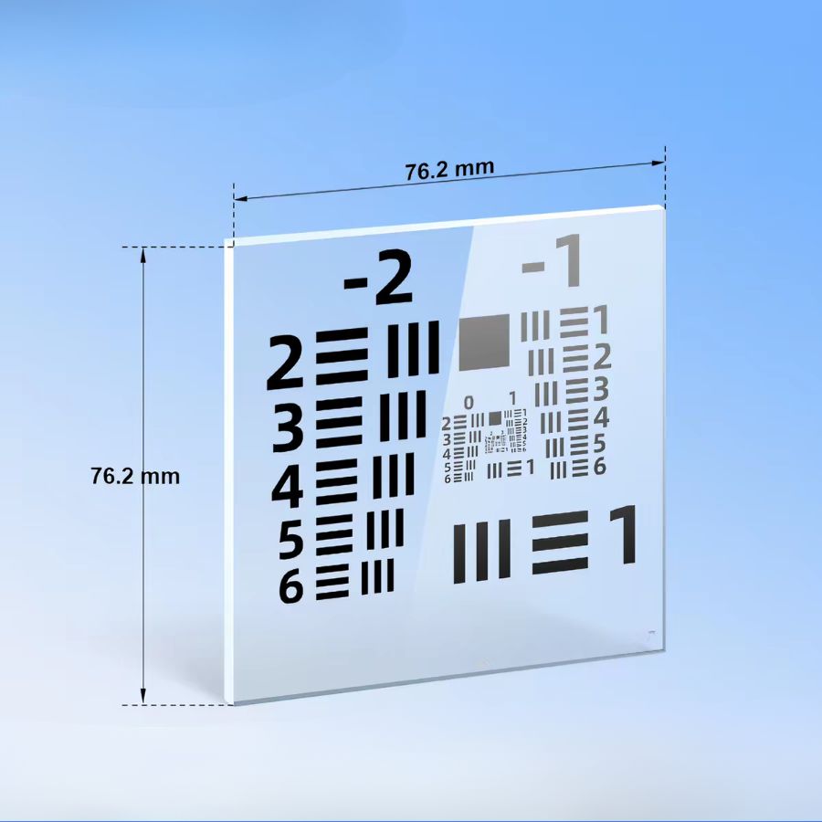
76.2 mm square
USAF horizontal and vertical three-bar groups with a dimensioned square substrate.
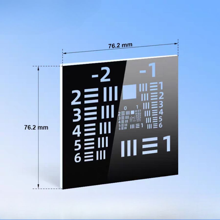
76.2 mm format
Opposite pattern polarity; confirm the required group range.
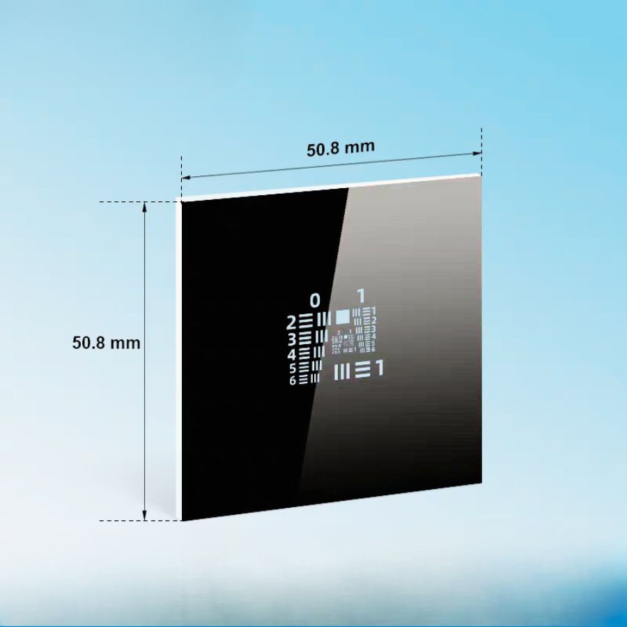
50.8 mm format
Small central pattern within a larger mounting area.
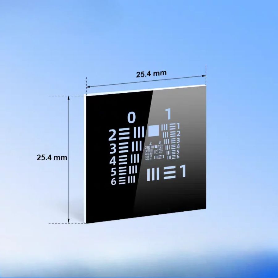
25.4 mm format
For a smaller mounting footprint.
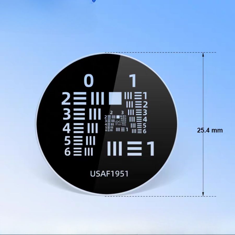
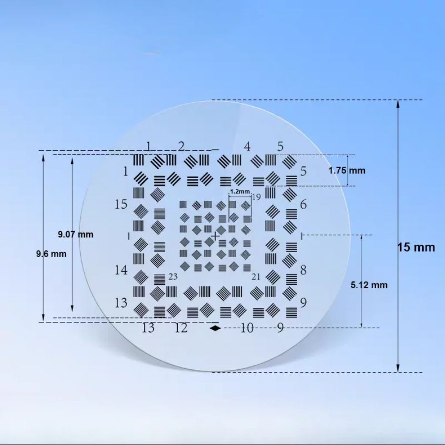
Ø25.4 mm
Circular substrate for a compatible optical holder.
15 mm reference format
The photograph compares two polarities; confirm the substrate outline in the drawing.
Checks resolved image detail as a separate test after geometric calibration.
Numbered three-bar elements for stepped resolution readings.
Inspection covers the critical bar widths, equal spaces, orientation, labels and clear/opaque defects. Target geometry and the imaging system’s resolved-detail result are assessed separately.
The supplied part is a patterned glass target in the selected range, polarity and substrate format. Any dimensional measurement record is identified in the order.
It means about 228 dark/light periods per millimetre at the stated plane. At group 7, element 6, the nominal frequency is 228.07 lp/mm and one equal-width bar is about 2.19 µm. It is not the same as 228 pixels per millimetre.
USAF 1951 resolution targets use labelled horizontal and vertical three-bar elements to compare detail resolved by cameras, microscopes and imaging optics.
For group g and element e, frequency is 2^(g + (e − 1)/6) lp/mm. Equal dark and bright widths are each 1/(2f) mm. Read all three bars and state target-plane or image-plane frequency.
Group and element range, polarity, plate format, substrate, magnification, lighting and reading criterion.
No. It is a discrete resolution reading under stated conditions. A frequency-response curve requires a corresponding SFR/MTF measurement method, and reappearing bars may be aliasing.