Dot array calibration targets
Known circle centres on patterned glass for camera calibration, geometric measurement and machine vision. Choose the array geometry around your software and working field.
Discuss your drawingView technical specifications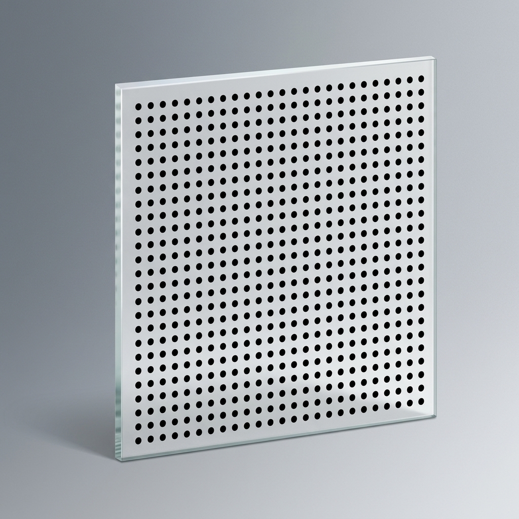
A reference made of points
A circle-grid target places dark or clear circular features at defined positions. Calibration software detects their image locations and pairs them with the physical coordinates on the plate. Images from several poses can then support camera intrinsic and lens-distortion estimation; a single view may support a defined planar mapping.
The board is a geometric reference. Calibration quality also depends on the lens, focus, lighting, image sampling and the software model.
Read the camera calibration guideWhy a circle grid?
Estimate a centre from the contour
A detector can fit the dot boundary or measure its centroid using many image pixels. Subpixel repeatability depends on sampling, focus, contrast and the detection method.
Cover the full imaging field
Distributed points provide coordinate references near the image centre and edges. Strong perspective, glare or blur still needs to be checked before accepting detections.
Keep point identity consistent
A supported asymmetric circle grid can help identify row order and board orientation in one image. The physical coordinate list must match the software in every camera view.
Choose the point layout
Start with the pattern your detector expects. The same-looking dots are not interchangeable when their coordinate order differs.
Rows and columns follow a rectangular coordinate grid. Specify both pitches, point count, origin and orientation.
Alternate rows are offset. Specify row spacing, in-row pitch, offset direction and the coordinate list used by the detector.
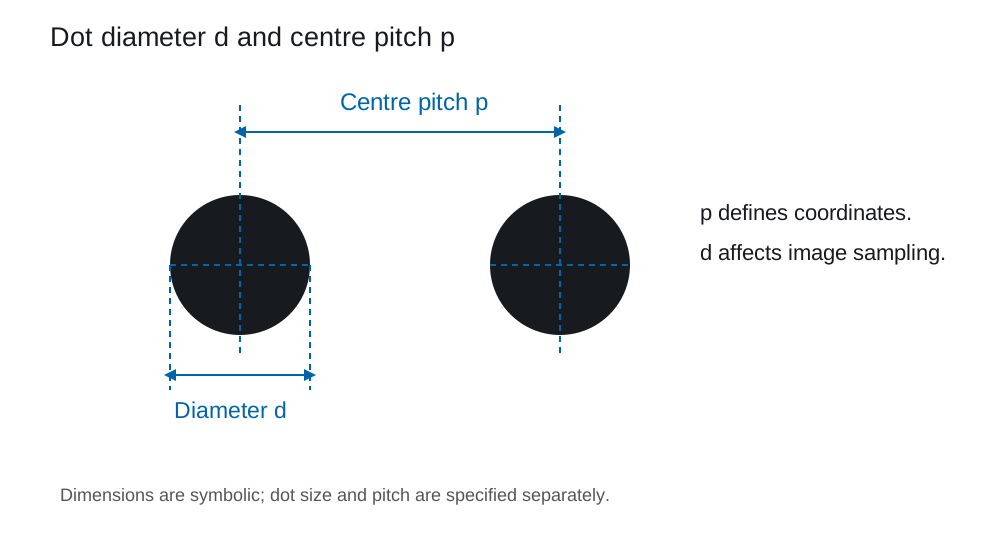
- Dot diameter
- Detection size
- Centre pitch
- Coordinate spacing
- Active area
- Field coverage
Technical specifications
Physical pattern tolerances and image-based centre detection are separate. Choose material and dimensions alongside the camera, lighting and detector.
Glass target
Fused silica or soda-lime glass with a photolithographic dot pattern.
| Substrate | Fused silica / soda-lime glass |
|---|---|
| Process | Photolithography |
| Line-width tolerance | ±0.2 µm |
| Minimum feature width | 0.55 µm or 1 µm, by pattern configuration |
| Feature and overall accuracy | ±1 µm |
| Clear-area transmission | >95% at 550 nm |
| Chrome finish | Yellow, low-reflection blue or bright chrome |
| Optical density | Yellow chrome OD 3; blue chrome OD 5 |
| Glass thickness | 1, 1.6, 2.3 or 3 mm (±0.2 mm) |
| Large-format glass thickness | 4.8 mm for the 500 × 500 mm format |
| Outline size | From 2 × 2 mm up to 800 × 960 mm |
| Outline tolerance at maximum format | ±0.1 mm at 800 × 960 mm |
| Fused-silica expansion | <5.0 × 10⁻⁷/K at 20–200°C |
| Low-reflection chrome reflectance | <13.4% at 550 nm; <1.8% at 650 nm; <2.67% at 750 nm |
| Surface flatness | <0.55 µm for lengths <50 mm; <2 µm for lengths <100 mm; <5 µm for lengths >100 mm |
| Chrome coating thickness | 120 ±5 nm (1200 ±50 Å) |
| Surface roughness | <0.025 µm |
| Optional white backing | 40 µm coating; 10 µm minimum feature width |
| Outline shape | Square |
| Pattern polarity | Opaque dots or clear dots |
Ceramic target
Opaque ceramic plates with matte or bright chrome patterns for reflective imaging.
| Substrate | Zirconia or alumina ceramic |
|---|---|
| Process | Photolithography |
| Line-width tolerance | ±0.2 µm |
| Pattern options | Matte chrome on matte ceramic; bright chrome on glossy ceramic |
| Minimum feature width | 4 µm matte; 2 µm glossy |
| Feature accuracy | ±2 µm |
| Outline accuracy | ±0.05 mm |
| Ceramic thickness | 1 mm (±0.1 mm), 2 mm or 3 mm (±0.1 mm) |
| Outline size | From 2 × 2 mm up to 228 × 228 mm |
| Outline size tolerance | ±0.1 mm at minimum and maximum formats |
| Flatness | <30 µm below 100 mm; <60 µm below 200 mm |
| Chrome coating | Matte chrome or bright chrome |
| Chrome thickness | 120 ±5 nm (1200 ±50 Å) |
| Surface roughness | 0.2–0.7 µm |
| Thermal expansion | <6.7 × 10⁻⁶/K at 40–400°C |
| Matte chrome reflectance | <12.88% at 550 nm; <10.62% at 650 nm; <12.23% at 750 nm |
| Bright chrome reflectance | <9.56% at 550 nm; <1.89% at 650 nm; <11.168% at 750 nm |
| Density | ≥3.66 g/cm³ |
| Rockwell hardness | ≥80 HRA |
| Optional protection | Thin protective layer above the chrome pattern |
| Edge and hole options | Laser-cut outline, hole, chamfer or bevel |
| Pattern polarity | Opaque pattern or clear pattern |
| Finish and shape | Matte or glossy; square, elliptical or drawing-defined cutouts |
Photographic film target
A thin, lightweight format for larger patterns where mounting and ambient conditions are controlled.
| Process | Photographic-film lithography |
|---|---|
| Application | Transmitted-light or backlit functional testing |
| Minimum feature width | 10 or 30 µm |
| Feature accuracy | ±10 µm |
| Film thickness | 0.18 mm (±0.01 mm) |
| Temperature-related dimensional change | 10 µm per °C per metre |
| Environmental response | Film dimensions also respond to humidity; control temperature and relative humidity during coordinate measurement |
| Emulsion | Silver halide, approximately 2 µm |
| Clear-area transmission | >90% across 400–700 nm |
| Optical density | OD >4 in solid black; grayscale density can be specified |
| Maximum format | 0.71 × 0.81 m at 10 µm minimum width; 1.68 × 3.5 m at 30 µm |
| Maximum-format tolerance | ±0.1 mm for both maximum formats |
| Pattern and cutting | Black, grayscale or sinusoidal grayscale; straight, laser-cut or perforated outline |
Choose the substrate
Match the plate material to illumination, working area, mounting and environmental conditions.
Glass
For transmitted-light imaging and a stable coordinate reference. Specify glass grade, thickness and pattern side for the optical path.
Ceramic
An opaque, rigid option for reflective setups. Surface finish and coordinate inspection should be defined for the application.
Film
A lightweight option for larger fields. Mounting, temperature and humidity need to be controlled when coordinates are measured.
Aluminum
For an opaque metal plate request, define surface finish, flatness and marking method in the drawing.
Specify what matters
Pattern geometry, optical contrast and inspection scope should follow the imaging setup. For glass boards, fused silica and soda-lime glass are available substrate families; grade and thickness follow the drawing.
Compare dots and checkerboardsPatternDot diameter, pitch, rows, columns, array type and origin.
Optical useTransmission or reflection, clear/opaque polarity and viewing side.
AcceptanceCentre positions, diameter, edge appearance and the measurement record required for the project.
Where it is used
Camera calibration and 3D visionUse known board coordinates across multiple views to estimate camera intrinsics and lens distortion before stereo reconstruction or monocular measurement.
Industrial metrology and photogrammetryDistributed circle centres support image-to-plane mapping and scale checks across the field when measuring large components or camera-guided assemblies.
Robot hand-eye calibrationUse the same board coordinate system across recorded robot poses to establish the camera-to-robot transform.
Before you order
Is a dot array always more accurate than a checkerboard?
No. Accuracy depends on manufactured coordinates, image sampling, illumination, viewpoint and the detection method. Compare both patterns under the intended imaging setup.
Which dimensions does calibration software need?
It needs the physical point coordinates or centre spacing and the correct row and column order. Dot diameter also matters for reliable detection, even when it is not part of the coordinate model.
Can the board use a staggered pattern?
Yes, when the row offsets and coordinate order match the software detector. A staggered pattern should be supplied with its coordinate definition and viewing side.
Available formats
Dense field
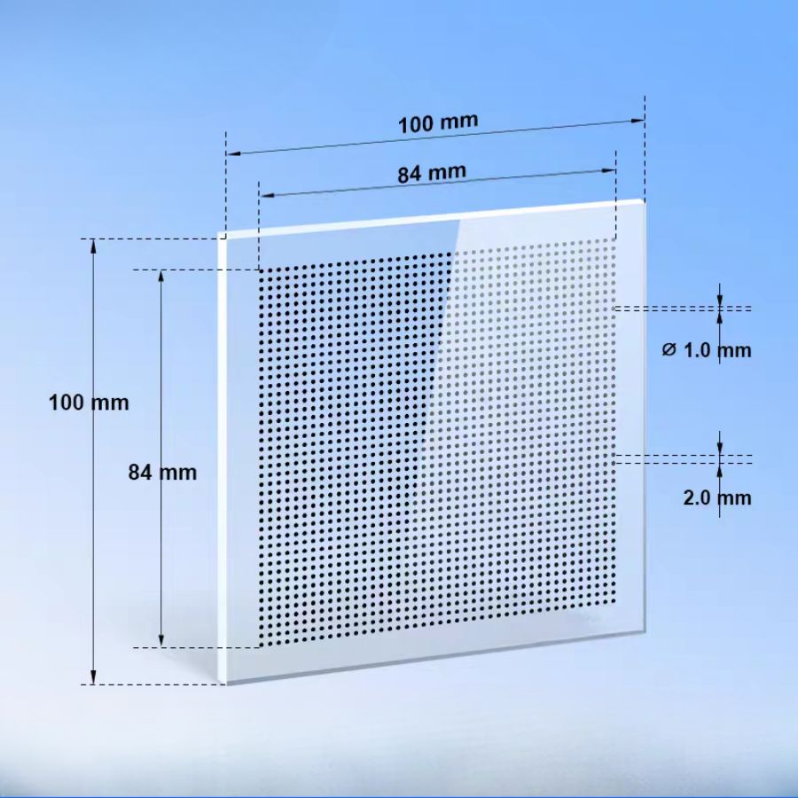
A dense array on a larger plate. The image identifies a 100 mm outline and an 84 mm patterned area; dot diameter and centre pitch are separate drawing dimensions.
Compact field
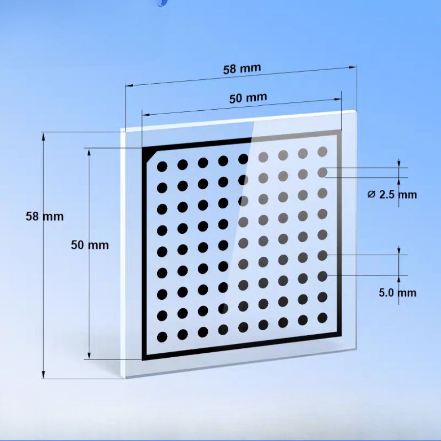
The pictured layout marks a 2.5 mm dot diameter and a 5.0 mm centre pitch. These belong to this illustrated format, not to every circle grid.
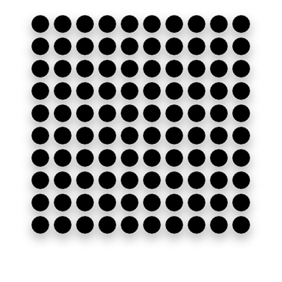
Pattern close-up
A close view makes dot separation and edge appearance easier to inspect. It does not establish the physical centre-coordinate tolerance.
Bring your drawing
Send the board geometry, software detector, working field and inspection priorities. We can review the pattern and glass configuration against your application.
Request a quoteSelection notes
Circle-grid calibration targets place circular light-and-dark features at known physical coordinates. The detector matches image centres to those coordinates to estimate camera intrinsics, lens distortion and target pose.
Specify dot diameter separately from centre spacing, rows, columns and origin. Symmetric and asymmetric layouts require the matching detector and coordinate convention; choose board size and illumination for the working field.
Information for your inquiry
Dot diameter, pitch, layout, rows and columns, active area, substrate, thickness, polarity, field of view and software.
Is finding a centre to a fraction of a pixel a guarantee of measurement accuracy?
Subpixel output is an estimated location. Defocus, reflections, perspective, sampling and manufactured geometry still affect the result; validate dimensions in the actual imaging configuration.