
Checkerboard calibration targets
Known internal corners for camera calibration, stereo vision and industrial measurement. Specify square pitch, corner count and substrate to match your camera, lighting and software.
Request a quoteView technical specifications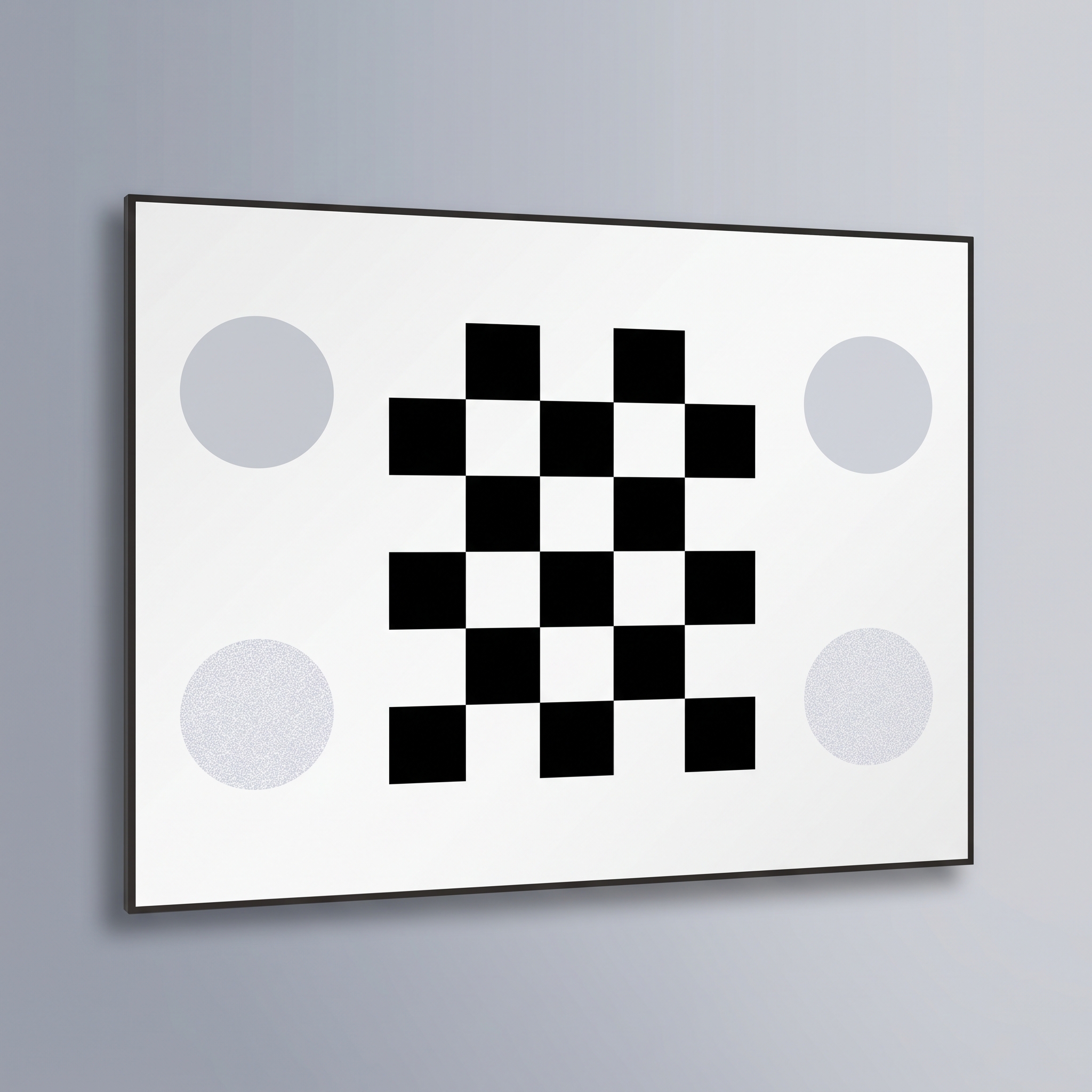
Technical specifications
Select the values for the actual substrate and process. Material properties and coating options do not automatically apply to every board; define acceptance values on the drawing.
Glass and fused silica
For transmitted light and dimensionally stable optical references.
| Patterning process | Photolithography |
|---|---|
| Photolithographic line-width tolerance | ±0.2 µm |
| Substrate options | Fused silica or soda-lime glass |
| Minimum line width | 1 µm / 0.55 µm |
| Feature and overall accuracy | ±1 µm |
| Coating options | Yellow chrome, low-reflection blue chrome or bright chrome |
| Selected coating reflectance | <13.4% at 550 nm; <1.8% at 650 nm; <2.67% at 750 nm |
| Coating thickness | 120 ±5 nm (1200 ±50 Å) |
| Optical density | OD 3 yellow chrome; OD 5 blue chrome |
| Clear-substrate transmission | >95% at 550 nm |
| Fused-silica thermal expansion (20–200 °C) | <5.0 × 10⁻⁷/K |
| Surface flatness by length | <0.55 µm below 50 mm; <2 µm below 100 mm; <5 µm above 100 mm |
| Surface roughness | <0.025 µm |
| Thickness options | 1, 1.6, 2.3 or 3 mm (±0.2 mm); 500 × 500 × 4.8 mm format |
| Size range | 2 × 2 mm minimum; 800 × 960 mm maximum (±0.1 mm) |
| Optional white backing | 40 µm rear coating; 10 µm minimum line width |
| Pattern polarity | Opaque pattern on clear field or clear pattern on opaque field |
Ceramic
For reflective industrial setups where surface finish and handling matter.
| Patterning process | Photolithography |
|---|---|
| Photolithographic line-width tolerance | ±0.2 µm |
| Substrate options | Zirconia or alumina |
| Finish options | Matte chrome on matte ceramic; bright chrome on polished ceramic |
| Minimum line width | 4 µm matte; 2 µm polished |
| Feature accuracy | ±2 µm |
| Outline accuracy | ±0.05 mm |
| Reflectance at 550 / 650 / 750 nm | Matte: <12.88% / <10.62% / <12.23%; polished: <9.56% / <1.89% / <11.168% |
| Chrome thickness | 120 ±5 nm (1200 ±50 Å) |
| Thickness options | 1 mm (±0.1 mm), 2 mm or 3 mm (±0.1 mm) |
| Surface flatness by length | <30 µm below 100 mm; <60 µm below 200 mm |
| Size range | 2 × 2 mm minimum; 228 × 228 mm maximum (±0.1 mm) |
| Surface roughness | 0.2–0.7 µm |
| Thermal expansion (40–400 °C) | <6.7 × 10⁻⁶/K |
| Density and hardness | ≥3.66 g/cm³; ≥80 HRA |
| Pattern polarity | Light and dark reflective patterns; transmitted-light polarity requires a transparent substrate |
| Outline and optional features | Square, elliptical or laser-cut profile; holes, chamfers and bevels |
| Optional protective layer | Thin film over chrome for improved pattern durability |
Photographic film
For large-format or lightweight transmissive targets.
| Patterning process | Film photolithography |
|---|---|
| Minimum line width | 10 µm or 30 µm |
| Feature accuracy | ±10 µm |
| Coating and thickness | Silver bromide, 2 µm |
| Optical density | OD >4 at full black; controllable grayscale |
| Tone options | Black or sinusoidal grayscale |
| Clear-area visible transmission | >90% at 400–700 nm |
| Substrate thickness | 0.18 mm (±0.01 mm) |
| Maximum size at 10 µm lines | 0.71 × 0.81 m (±0.1 mm) |
| Maximum size at 30 µm lines | 1.68 × 3.5 m (±0.1 mm) |
| Dimensional change | 10 µm per °C per metre under specified humidity; control temperature and humidity in use |
| Cutting options | Laser cutting, straight cutting or circular cut-outs |
Define the corners your software reads
A checkerboard corner is where four alternating squares meet. C columns by R rows of complete squares provide (C − 1) by (R − 1) internal corners. The physical square pitch sets their coordinate spacing; record row and column order in the same orientation used by the detector.
- Pattern
- Alternating dark and light squares
- Field
- Reflective or transmissive, by configuration
- Coordinate input
- Inner corners and square pitch
- Viewing side
- Defined on the drawing
Choose material with the light path
Glass and fused silica
Transparent substrates can carry photolithographic chrome squares. Define material grade, active-area flatness, coating and whether the light field stays clear or receives a white backing.
Ceramic and film
Ceramic supports a reflective, durable pattern but does not transmit light. Film supports larger lightweight patterns; mounting and temperature or humidity changes can affect coordinate stability.
Larger or permanent installations
Carbon-fibre composite and metal plate may be considered when mass, stiffness or handling matters. Their patterning and flatness requirements must be specified for the actual construction, not borrowed from glass or ceramic tables.
Accuracy starts at the working plane
A planar calibration model uses known corner positions in one plane. Pattern pitch, corner placement and flatness in the installed state all matter. A numerical subpixel corner estimate is not proof that the physical target or completed calibration has subpixel accuracy.
Use enough board positions and tilts to cover the image field. Inspect detected-corner order, glare and focus, then review residuals and an independent measurement before accepting the camera model.
Edge definition
Sharp, consistent light-to-dark transitions help the detector locate corners. Inspect edge defects and local contrast under the actual lighting and exposure.
Reflection control
A matte finish or low-reflection coating can reduce highlights in reflected light. Choose the surface finish for the illumination geometry rather than assuming one finish suits both reflection and transmission.
Where it is used
Camera intrinsics and distortionKnown physical corners captured across the image support estimation of focal parameters, principal point and lens distortion.
Stereo and 3D visionBoth cameras observe the same grid to estimate relative pose. Keep detectable corners inside their overlapping field of view.
Measurement and robot visionVerified corner coordinates support dimensional inspection and board-pose estimation. For hand-eye calibration, combine camera observations with recorded robot poses and validate the complete coordinate transform.
Specify the board on your drawing
Send square pitch, square and internal-corner counts, active area, outline, substrate and thickness, pattern polarity, viewing side, lighting and the inspection values you need recorded.
Common questions
Which material fits backlit calibration?
Use a transparent substrate such as glass or film when the pattern must be viewed in transmitted light. Ceramic is opaque and is normally read by reflected light. Choose the coating polarity for the detector and lighting arrangement.
Why does target flatness matter?
Planar calibration assumes known points lie on one plane. Board bowing can bias the fitted camera model, so specify and inspect flatness in the working mount when dimensional accuracy matters.
How do reflections affect corner detection?
A bright reflection can reduce contrast or saturate part of the pattern, shifting detected corners. Match surface finish and coating to the illumination and check captures across the full image field.
How large should the board be?
Choose the active pattern size from working distance and field of view, then set square pitch so corners remain detectable at the edges and under intended tilts. Plate outline, pattern area and square pitch are separate dimensions.
Does a checkerboard measure lens resolution?
Its main purpose is geometric calibration. Use bar, star or slanted-edge targets with a suitable method to assess detail or frequency response. A geometric calibration result does not establish optical resolving power.
Does a smaller square improve calibration?
Smaller squares provide more features only while their corners remain detectable. Blur, sampling, tilt and illumination can make a dense board less useful. Match pitch to the working distance and edge-of-field image quality.
Can the board be viewed through the back of the glass?
The film side normally gives direct access to the patterned plane. Viewing through the substrate introduces refraction and may mirror the coordinate orientation. Use a model and coordinate definition appropriate to that arrangement, especially with tilted views.
Formats and pattern options
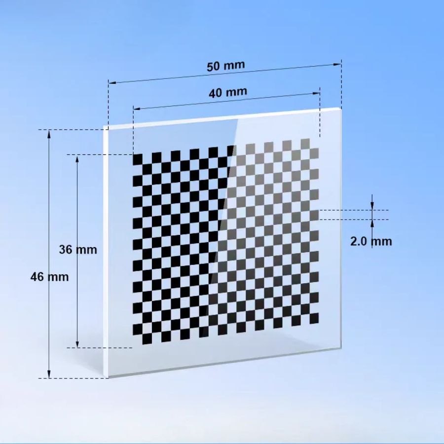
Checkerboard / compact format
50 mm plate
Compact plate for a smaller working field; select pitch so the farthest corners remain detectable.
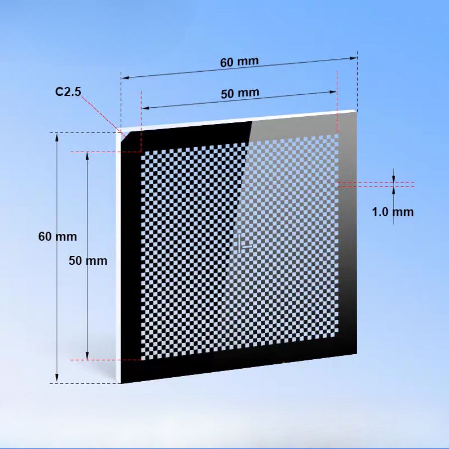
Checkerboard / medium format
60 mm plate
Medium plate with a border around the pattern. Reserve clear space for the detector and fixture.
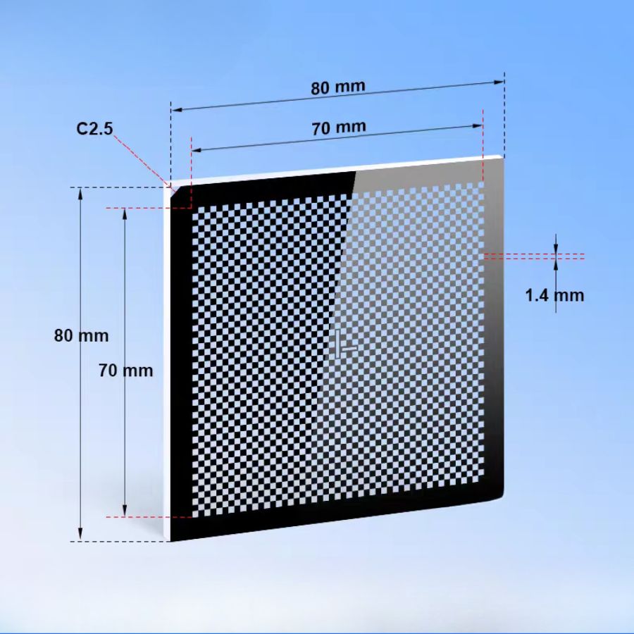
Checkerboard / larger format
80 mm plate
Larger plate area for wider field coverage. Specify square pitch independently from glass dimensions.

Checkerboard / dense large format
110 mm plate
Dense pattern on a larger plate. Check corner sampling and depth of field at the required viewing angles.
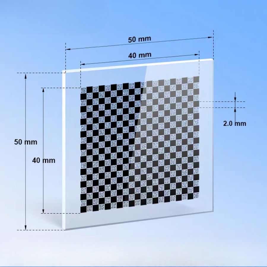
Checkerboard / alternate view
50 mm plate
An additional view of the 50 mm family; use the same coordinate definition when comparing configurations.
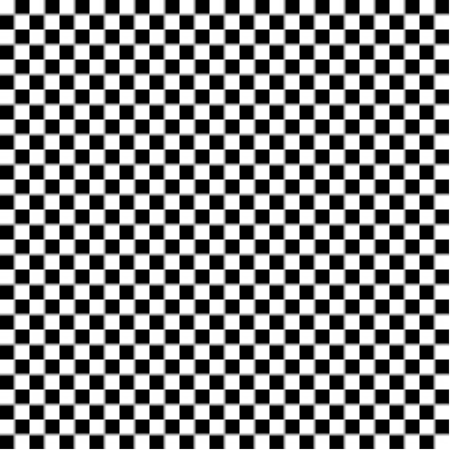
R80W
Pattern reference
A drawing-defined chequerboard pattern. Confirm the artwork revision, square count and pitch before use.
Selection notes
Checkerboard calibration targets provide known planar inner corners for fitting camera intrinsics, distortion and pose.
Define square pitch, visible square count and inner-corner count separately. A 10 × 7-square board has 9 × 6 inner corners; a 12 × 9-square board has 11 × 8.
Information for your inquiry
Square pitch, squares and inner corners in each direction, border, active field, polarity, material and software.
Does the board alone determine final measurement accuracy?
The board supplies physical geometry. Image coverage, focus, camera model, mounting and independent validation also determine usable system accuracy.