Detect the internal corners
Pass the inner-corner count, not the square count, to findChessboardCorners or findChessboardCornersSB. The entire pattern should be sharp and visible.

Drawing-defined checkerboards for camera and stereo calibration. Specify physical square pitch and internal corner count together.
Request a quoteView technical specifications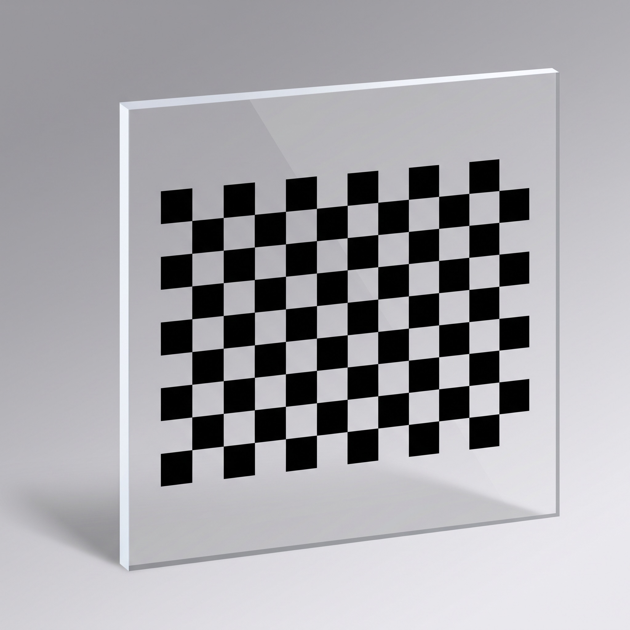
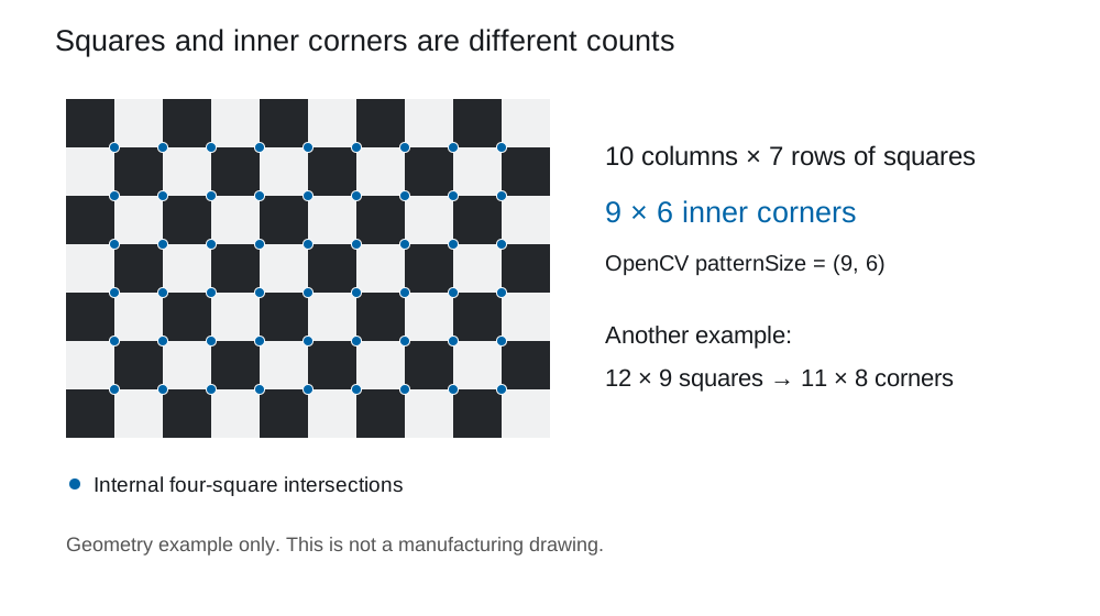
OpenCV identifies intersections inside the alternating-square pattern. A 10-column by 7-row board has 9 columns by 6 rows of internal corners. This count is the patternSize supplied to the detector; the physical square pitch defines the scale of the object coordinates.
A checkerboard needs no separate pattern description file, but the drawing, measured pitch and software model must still refer to the same board revision.
Internal corners
patternSize (9, 6)Internal corners
patternSize (11, 8)The board supplies physical coordinates. The image supplies detected corners. Calibration only makes sense when both use the same geometry and point order.
Pass the inner-corner count, not the square count, to findChessboardCorners or findChessboardCornersSB. The entire pattern should be sharp and visible.
For the classic detector, cornerSubPix refines detected positions using the local image gradients. The SB detector returns subpixel positions directly. Review ordering and failed views before calibration.
Generate planar object coordinates from the measured square pitch, then use calibrateCamera. Inspect the reprojection residuals across views and validate the model at the intended working distance.
Set the physical distance between adjacent inner corners. The software model must use the same measured unit and pitch.
A board with 10 × 7 squares has 9 × 6 internal corners. Record column and row order with the drawing.
Keep the entire grid visible in both cameras when calibrating stereo systems. Leave a clear border and choose pattern polarity for the lighting mode.
Choose glass, ceramic or film according to illumination, plate size and dimensional stability. Specify the pattern side and viewing direction.
calibrateCamera estimates focal lengths, the principal point, distortion coefficients and a pose for each view. Radial terms describe effects such as barrel or pincushion distortion; tangential terms account for another component of image displacement. Choose additional distortion terms only when the lens and observations support a more complex model.
For stereoCalibrate, both cameras observe the same complete board at several poses. The resulting relative rotation and translation support rectification and depth estimation. The board must remain inside the overlapping fields of view, and scale comes from its physical square pitch.
OpenCV supports both checkerboards and symmetric or asymmetric circle grids. Checkerboards use internal corners; circle grids use detected dot centres. Compare their detection stability under the actual focus, lighting and field of view instead of assuming one geometry is always more accurate.
Glass, ceramic and film are different manufacturing options. Select the pattern, substrate and inspection requirements on the approved drawing.
Fused silica or soda-lime glass with a photolithographic checkerboard pattern.
| Substrate | Fused silica / soda-lime glass |
|---|---|
| Process | Photolithography |
| Line-width tolerance | ±0.2 µm |
| Minimum feature width | 0.55 µm or 1 µm, by pattern configuration |
| Feature and overall accuracy | ±1 µm |
| Clear-area transmission | >95% at 550 nm |
| Chrome finish | Yellow, low-reflection blue or bright chrome |
| Optical density | Yellow chrome OD 3; blue chrome OD 5 |
| Glass thickness | 1, 1.6, 2.3 or 3 mm (±0.2 mm) |
| Large-format glass thickness | 4.8 mm for the 500 × 500 mm format |
| Outline size | From 2 × 2 mm up to 800 × 960 mm |
| Outline tolerance at maximum format | ±0.1 mm at 800 × 960 mm |
| Fused-silica expansion | <5.0 × 10⁻⁷/K at 20–200°C |
| Low-reflection chrome reflectance | <13.4% at 550 nm; <1.8% at 650 nm; <2.67% at 750 nm |
| Surface flatness | <0.55 µm for lengths <50 mm; <2 µm for lengths <100 mm; <5 µm for lengths >100 mm |
| Chrome coating thickness | 120 ±5 nm (1200 ±50 Å) |
| Surface roughness | <0.025 µm |
| Optional white backing | 40 µm coating; 10 µm minimum feature width |
| Outline shape | Square |
| Pattern polarity | Opaque squares or clear squares, according to artwork polarity |
Opaque ceramic with matte or bright chrome checkerboard features for reflected-light imaging.
| Substrate | Zirconia or alumina ceramic |
|---|---|
| Process | Photolithography |
| Line-width tolerance | ±0.2 µm |
| Pattern options | Matte chrome on matte ceramic; bright chrome on glossy ceramic |
| Minimum feature width | 4 µm matte; 2 µm glossy |
| Feature accuracy | ±2 µm |
| Outline accuracy | ±0.05 mm |
| Ceramic thickness | 1 mm (±0.1 mm), 2 mm or 3 mm (±0.1 mm) |
| Outline size | From 2 × 2 mm up to 228 × 228 mm |
| Outline size tolerance | ±0.1 mm at minimum and maximum formats |
| Flatness | <30 µm below 100 mm; <60 µm below 200 mm |
| Chrome coating | Matte chrome or bright chrome |
| Chrome thickness | 120 ±5 nm (1200 ±50 Å) |
| Surface roughness | 0.2–0.7 µm |
| Thermal expansion | <6.7 × 10⁻⁶/K at 40–400°C |
| Matte chrome reflectance | <12.88% at 550 nm; <10.62% at 650 nm; <12.23% at 750 nm |
| Bright chrome reflectance | <9.56% at 550 nm; <1.89% at 650 nm; <11.168% at 750 nm |
| Density | ≥3.66 g/cm³ |
| Rockwell hardness | ≥80 HRA |
| Optional protection | Thin protective layer above the chrome pattern |
| Edge and hole options | Laser-cut outline, hole, chamfer or bevel |
| Pattern polarity | Dark or light squares on an opaque ceramic surface; use reflected light |
| Finish and shape | Matte or glossy; square, elliptical or drawing-defined cutouts |
Thin photographic film carrying a checkerboard pattern for larger transmitted-light setups.
| Process | Photographic-film lithography |
|---|---|
| Application | Transmitted-light or backlit functional testing |
| Minimum feature width | 10 or 30 µm |
| Feature accuracy | ±10 µm |
| Film thickness | 0.18 mm (±0.01 mm) |
| Temperature-related dimensional change | 10 µm per °C per metre |
| Environmental response | Film dimensions also respond to humidity; control temperature and relative humidity during coordinate measurement |
| Emulsion | Silver halide, approximately 2 µm |
| Clear-area transmission | >90% across 400–700 nm |
| Optical density | OD >4 in solid black; grayscale density can be specified |
| Maximum format | 0.71 × 0.81 m at 10 µm minimum width; 1.68 × 3.5 m at 30 µm |
| Maximum-format tolerance | ±0.1 mm for both maximum formats |
| Pattern and cutting | Black, grayscale or sinusoidal grayscale; straight, laser-cut or perforated outline |
Rigid aluminium is an option for larger reflected-light targets. Define the square geometry, surface finish, dimensions and tolerances on the drawing.
Camera and lens calibrationEstimate focal parameters, principal point and lens distortion from views taken at different positions and tilts.
Stereo and 3D visionImage the same complete board in both cameras to estimate their relative pose before rectification and depth measurement.
Industrial measurementUse the calibrated camera model to relate image measurements to a defined plane or another known depth constraint.
Robotics and photogrammetryUse target observations in camera pose estimation, hand-eye calibration or multi-view reconstruction workflows.
Wide-angle and endoscopic opticsCharacterise distortion for surveillance cameras, endoscopes and other lenses when the calibration field and target size are suitable.
Imaging and research systemsSupport lens profiling, multi-camera alignment, UAV imaging and laboratory instruments that use cameras for measurement.
It counts internal corners, ordered as columns and rows. A 10 × 7-square board has patternSize (9, 6).
Yes. OpenCV has findCirclesGrid for symmetric and asymmetric circle patterns. Select the detector that matches the actual target; neither pattern is inherently more accurate in every setup.
The classic findChessboardCorners path is normally followed by cornerSubPix. findChessboardCornersSB is another option and returns subpixel coordinates directly. Test both with images from the real setup.
Check the inner-corner count and row order, full board visibility, focus, reflections and contrast. A border around the active pattern can help the detector separate it from the background.
There is no universal count. Capture varied tilts, image positions and working distances, then assess per-view residuals and independent measurement error.
calibrateCamera reports an overall RMS reprojection error in pixels. Examine per-view residuals and independent measurements as well: a low aggregate error alone does not establish dimensional accuracy.
Send the square pitch, inner-corner count, board dimensions, substrate, illumination mode, pattern side and drawing revision. State any inspection tolerance separately.
Share the drawing, square pitch, internal corner count, board dimensions, lighting mode and required substrate.
Request a quoteOpenCV checkerboard targets provide known inner-corner coordinates for camera and stereo calibration workflows.
Set patternSize to inner-corner columns and rows, not square count. Generate object points using the actual square pitch; findChessboardCornersSB and the classic detector have different detection and refinement paths.
OpenCV version, detector, inner-corner count, square pitch, border, material, polarity and intended camera setup.
No. The object-point array supplies the physical pitch and units. Keep its point order identical to the detected image corners before calibrating or estimating pose.