
Negative checkerboard
Clear squares in an opaque field give a backlit camera a defined grid of internal corners. Specify the geometry, substrate and pattern polarity together.
Request a quoteView technical specifications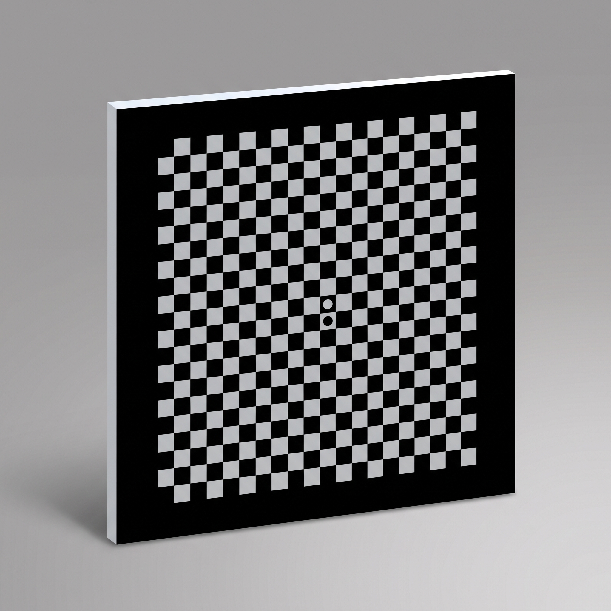
Specify the pattern first
For a board with C × R squares, the internal-corner array is (C − 1) × (R − 1). Specify square pitch, board outline, clear/opaque orientation and the patterned face together on the drawing.
- Pattern polarity
- Clear squares / opaque field
- Imaging mode
- Backlit transmission
- Coordinate input
- Inner corners and square pitch
- Supply format
- Glass or film; to drawing
Technical specifications
Choose the substrate and applicable process values for the working wavelength, field and mounting. Confirm acceptance values on the drawing.
Glass target
Transparent glass with clear checkerboard squares in an opaque chromium field for transmitted light. Confirm the material grade and wavelength on the drawing.
| Substrate | Fused silica / soda-lime glass |
|---|---|
| Process | Photolithography |
| Line-width tolerance | ±0.2 µm |
| Minimum feature width | 0.55 µm or 1 µm, by pattern configuration |
| Feature and overall accuracy | ±1 µm |
| Clear-area transmission | >95% at 550 nm |
| Chrome finish | Yellow, low-reflection blue or bright chrome |
| Optical density | Yellow chrome OD 3; blue chrome OD 5 |
| Glass thickness | 1, 1.6, 2.3 or 3 mm (±0.2 mm) |
| Large-format glass thickness | 4.8 mm for the 500 × 500 mm format |
| Outline size | From 2 × 2 mm up to 800 × 960 mm |
| Outline tolerance at maximum format | ±0.1 mm at 800 × 960 mm |
| Fused-silica expansion | <5.0 × 10⁻⁷/K at 20–200°C |
| Low-reflection chrome reflectance | <13.4% at 550 nm; <1.8% at 650 nm; <2.67% at 750 nm |
| Surface flatness | <0.55 µm for lengths <50 mm; <2 µm for lengths <100 mm; <5 µm for lengths >100 mm |
| Chrome coating thickness | 120 ±5 nm (1200 ±50 Å) |
| Surface roughness | <0.025 µm |
| Optional white backing | 40 µm coating; 10 µm minimum feature width |
| Outline shape | Square |
| Checkerboard polarity | Clear squares in an opaque field; confirm the exact alternating-square artwork |
Ceramic target
Opaque ceramic is a reflected-light alternative. It cannot provide transmitting squares or replace a backlit negative glass target.
| Substrate | Zirconia or alumina ceramic |
|---|---|
| Process | Photolithography |
| Line-width tolerance | ±0.2 µm |
| Pattern options | Matte chrome on matte ceramic; bright chrome on glossy ceramic |
| Minimum feature width | 4 µm matte; 2 µm glossy |
| Feature accuracy | ±2 µm |
| Outline accuracy | ±0.05 mm |
| Ceramic thickness | 1 mm (±0.1 mm), 2 mm or 3 mm (±0.1 mm) |
| Outline size | From 2 × 2 mm up to 228 × 228 mm |
| Outline size tolerance | ±0.1 mm at minimum and maximum formats |
| Flatness | <30 µm below 100 mm; <60 µm below 200 mm |
| Chrome coating | Matte chrome or bright chrome |
| Chrome thickness | 120 ±5 nm (1200 ±50 Å) |
| Surface roughness | 0.2–0.7 µm |
| Thermal expansion | <6.7 × 10⁻⁶/K at 40–400°C |
| Matte chrome reflectance | <12.88% at 550 nm; <10.62% at 650 nm; <12.23% at 750 nm |
| Bright chrome reflectance | <9.56% at 550 nm; <1.89% at 650 nm; <11.168% at 750 nm |
| Density | ≥3.66 g/cm³ |
| Rockwell hardness | ≥80 HRA |
| Optional protection | Thin protective layer above the chrome pattern |
| Edge and hole options | Laser-cut outline, hole, chamfer or bevel |
| Finish and shape | Matte or glossy; square, elliptical or drawing-defined cutouts |
| Checkerboard polarity | Reflective light/dark squares on opaque ceramic; no transmitted-light option |
Photographic film target
Photographic film can carry clear squares in an opaque field for a larger backlit pattern when mounting, temperature and humidity are controlled.
| Process | Photographic-film lithography |
|---|---|
| Application | Transmitted-light or backlit functional testing |
| Minimum feature width | 10 or 30 µm |
| Feature accuracy | ±10 µm |
| Film thickness | 0.18 mm (±0.01 mm) |
| Temperature-related dimensional change | 10 µm per °C per metre |
| Environmental response | Film dimensions also respond to humidity; control temperature and relative humidity during coordinate measurement |
| Emulsion | Silver halide, approximately 2 µm |
| Clear-area transmission | >90% across 400–700 nm |
| Optical density | OD >4 in solid black; grayscale density can be specified |
| Maximum format | 0.71 × 0.81 m at 10 µm minimum width; 1.68 × 3.5 m at 30 µm |
| Maximum-format tolerance | ±0.1 mm for both maximum formats |
| Pattern and cutting | Black, grayscale or sinusoidal grayscale; straight, laser-cut or perforated outline |
| Checkerboard polarity | Clear squares in an opaque field; confirm the exact alternating-square artwork |
Geometry the camera can trust
A checkerboard corner is the meeting point of four alternating squares. A calibration program pairs detected image corners with known coordinates on the board. The point order and physical pitch must match; a 10 × 7-square board supplies 9 × 6 internal corners, not 10 × 7.
Use several views at different positions and tilts to cover the image field. Keep corners sharp and visible, then inspect per-view reprojection residuals. A target alone does not establish camera accuracy or replace a suitable calibration procedure.
Flatness and placement
A planar calibration model assumes the physical corner coordinates lie on one plane. Define active-area flatness, mounting stress and feature-position tolerance according to the measurement task.
Edges and illumination
Corner detection depends on a clean intensity transition. Inspect line edges and coating defects; choose backlight uniformity and exposure so highlights or saturation do not shift detected positions.
Select the substrate around the light path
Glass and fused silica
Polished transparent substrates support a chromium negative pattern and transmitted illumination. Choose the grade, thickness, surface and coating for the working wavelength and mounting format.
Photographic film
A lightweight option for larger backlit patterns. Define the frame and environmental conditions because temperature and humidity affect coordinate stability.
Opaque alternatives
Ceramic, carbon-fibre composite and metal can be considered for reflected-light checkerboards where surface finish, stiffness, weight or durability matters. They do not create transmitting squares in this negative glass configuration.
Where it is used
Camera intrinsics and distortionKnown corner coordinates from varied board poses support estimation of focal parameters, principal point and lens distortion.
Stereo and 3D visionBoth cameras observe the same board to estimate their relative pose; keep the active grid inside the overlapping field of view.
Industrial measurementA measured grid helps establish image geometry for dimensional inspection when target coordinates, setup and uncertainty are controlled.
Define the board on your drawing
Specify square pitch, square and internal-corner counts, active field, board outline, substrate and thickness, pattern side, clear/opaque orientation, working wavelength, illumination and the required inspection record.
Common questions
What makes this checkerboard a negative target?
The surrounding field is opaque and the designated squares are clear in the pattern layer. Backlighting makes the clear areas bright. State the exact polarity in the artwork because the word “negative” alone does not define every square.
How do square counts relate to internal corners?
A board with C columns and R rows of complete squares has (C − 1) columns and (R − 1) rows of internal corners. Give the physical square pitch and the same row/column order to the detector.
Can ceramic or metal make a transmitted-light version?
No. These opaque substrates can carry a high-contrast checkerboard for reflected-light imaging, but transmitted light requires a transparent substrate or suitable film.
Does a smaller square always improve calibration?
No. The corners must remain resolved across the field at the actual working distance. Choose pitch and board size together, then assess detection and reprojection residuals using real images.
What must be checked before ordering?
Send the drawing revision, square pitch, square and internal-corner counts, active area, substrate, coating polarity, viewing side, lighting mode and required inspection record.
Selection notes
Negative checkerboard targets use transmitting square regions within an opaque pattern for suitable backlit calibration setups.
Specify the complete border and corner geometry rather than inverting a preview alone. Check feature visibility, exposure and the software's expected polarity.
Information for your inquiry
Square pitch, inner corners, border, clear regions, substrate, active field and backlight.
Is a negative board detected identically by every checkerboard algorithm?
Detector assumptions vary. Verify the chosen detector, border, illumination and point order using the actual pattern and software version.