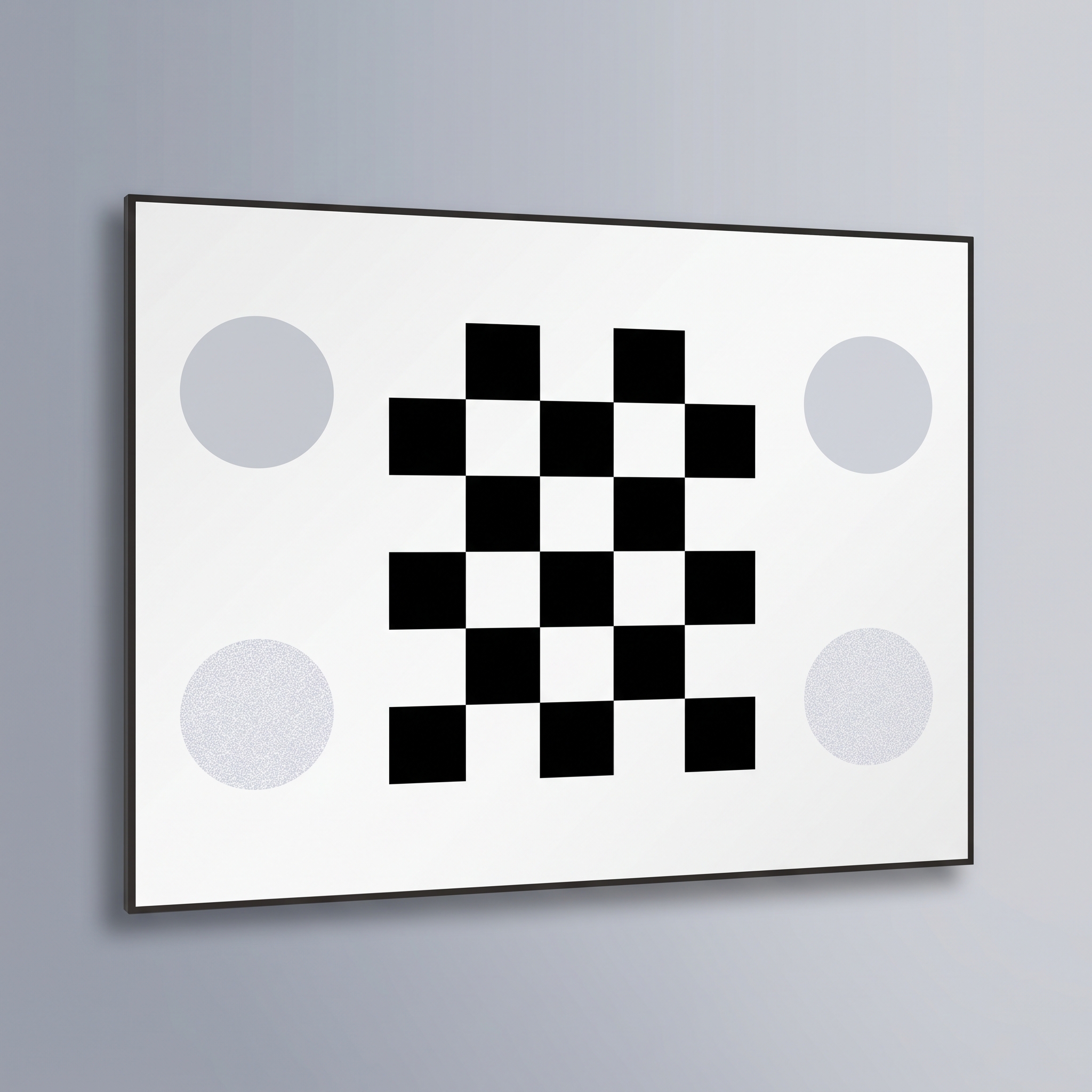
Checkerboard Calibration Targets
Checkerboard calibration targets in glass, ceramic and film for camera intrinsics, lens distortion and stereo vision. Specify square pitch, corner count, material and plate format.

Dot arrays, grids and checkerboards for camera calibration, image scale, distortion and coordinate alignment.
Choose the feature type your calibration software detects reliably. Define the coordinate system, active field and physical feature positions before selecting pitch and substrate format.
Start with the result you need: smallest visible detail, a frequency-response curve, camera geometry or a conversion from pixels to length. Select the pattern for that result before choosing its size.
Checkerboards, dots and grids describe image geometry. Resolution charts describe detail reproduction. A calibration workflow may need both, but they answer different questions.
Pattern size, feature spacing, polarity, usable field, substrate outline and mounting references can be selected around the camera and illumination. Measured geometry and traceable calibration are separate documentation requirements.
A glass target in the selected pattern, polarity and substrate format, with the dimensional inspection or calibration records included in the order.
Checkerboard calibration targets in glass, ceramic and film for camera intrinsics, lens distortion and stereo vision. Specify square pitch, corner count, material and plate format.
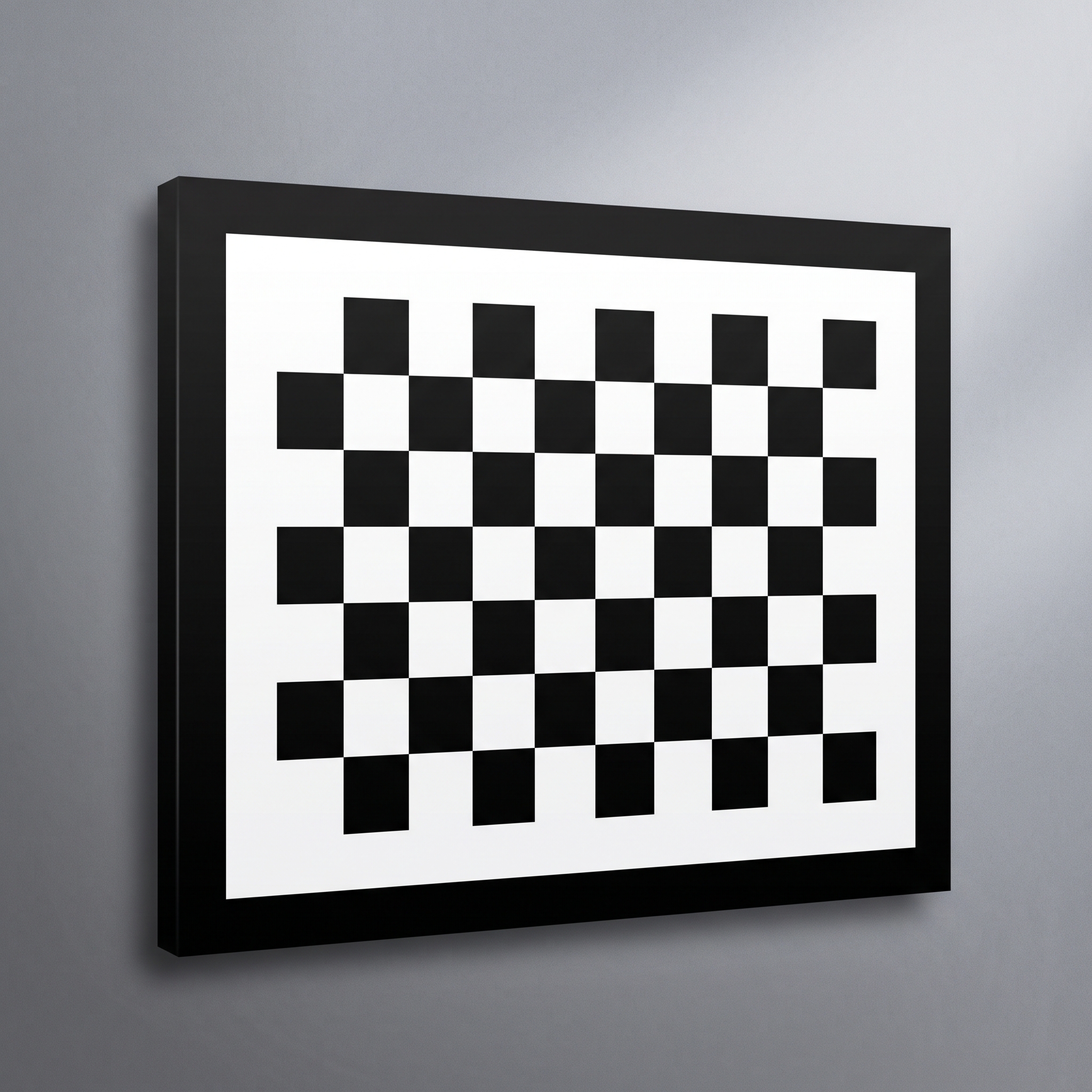
Positive checkerboard calibration targets with opaque dark squares on a contrasting clear or white field. Specify square pitch, inner-corner count, substrate and viewing conditions for camera calibration.
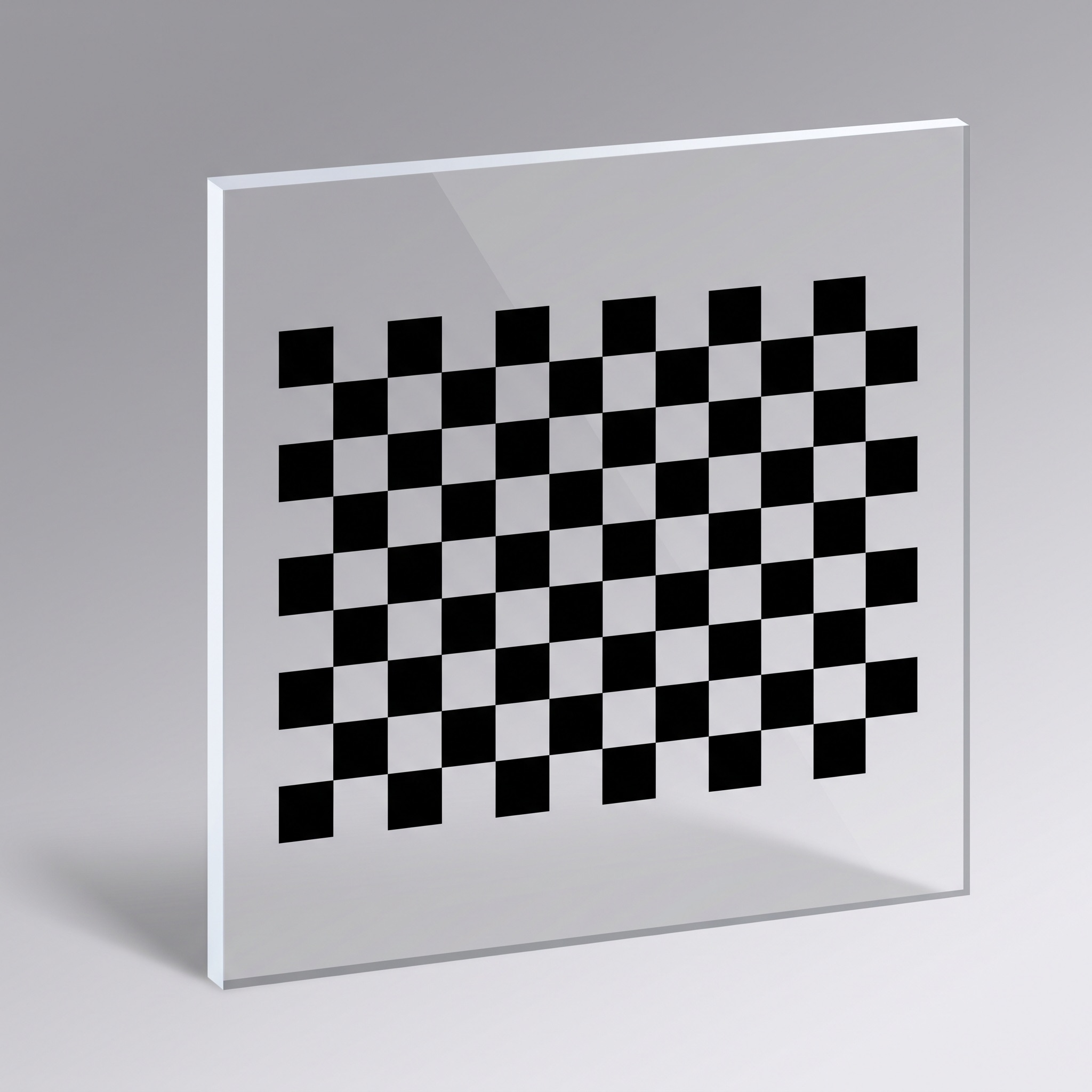
OpenCV chessboard calibration targets with drawing-defined square pitch and inner-corner count for camera and stereo calibration. Glass, ceramic and film options.
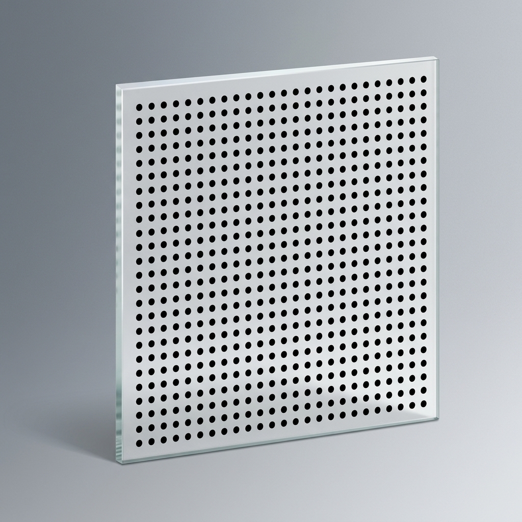
Glass dot-array calibration targets for camera geometry, stereo vision and measurement. Compare dot diameter, centre pitch, symmetric and staggered circle grids.
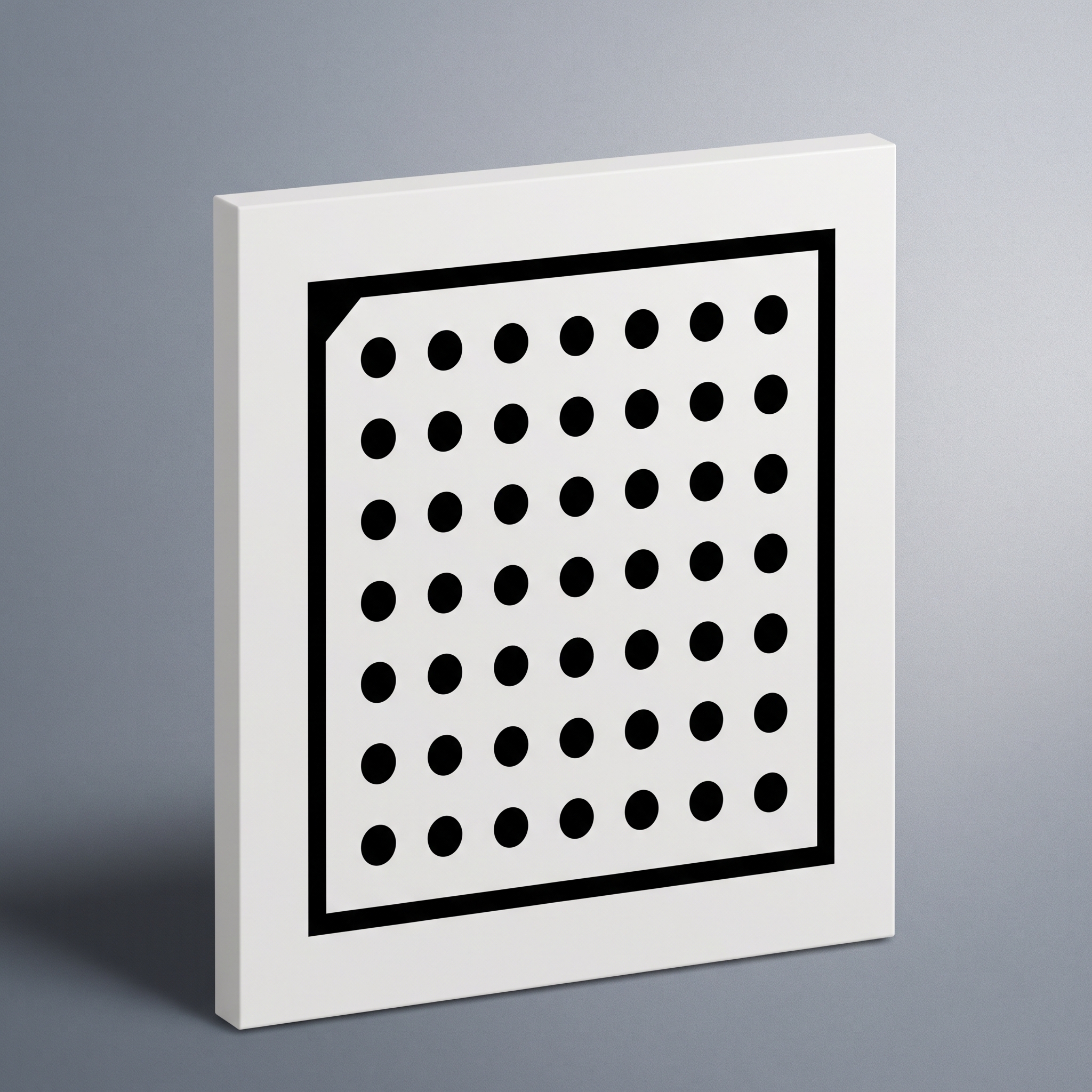
Drawing-defined circle-grid calibration targets for HALCON camera calibration workflows, with matching geometry and calibration-object description data.
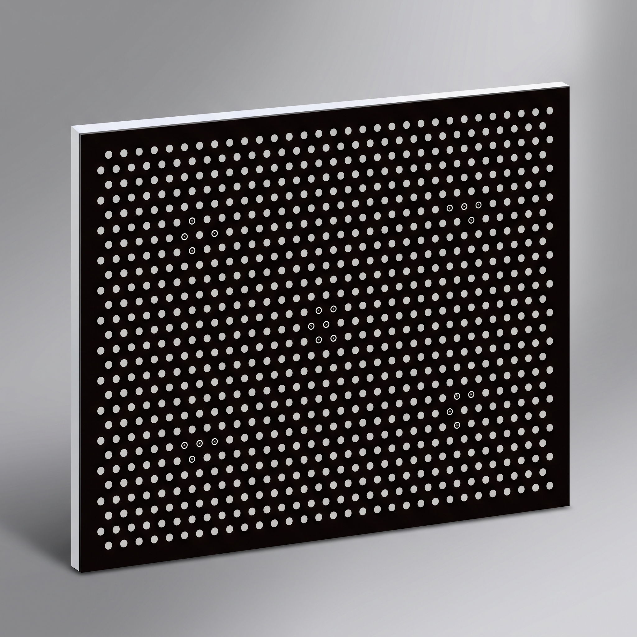
Hexagonal circle-grid calibration targets with finder patterns and matching .cpd description data for HALCON camera calibration.
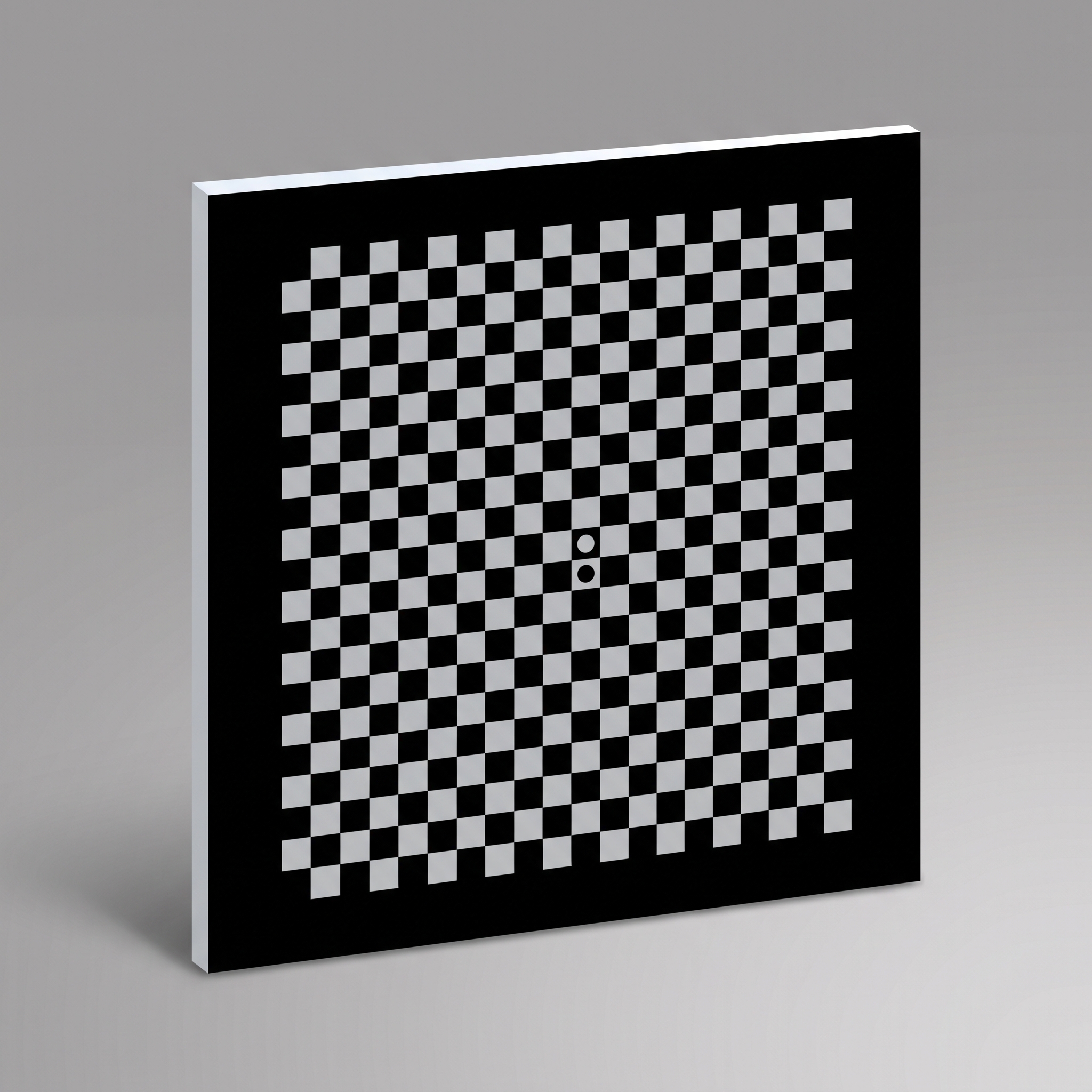
Negative-polarity checkerboard calibration targets with clear squares in an opaque field for backlit camera and stereo calibration. Compare glass and film formats, grid geometry and inspection requirements.
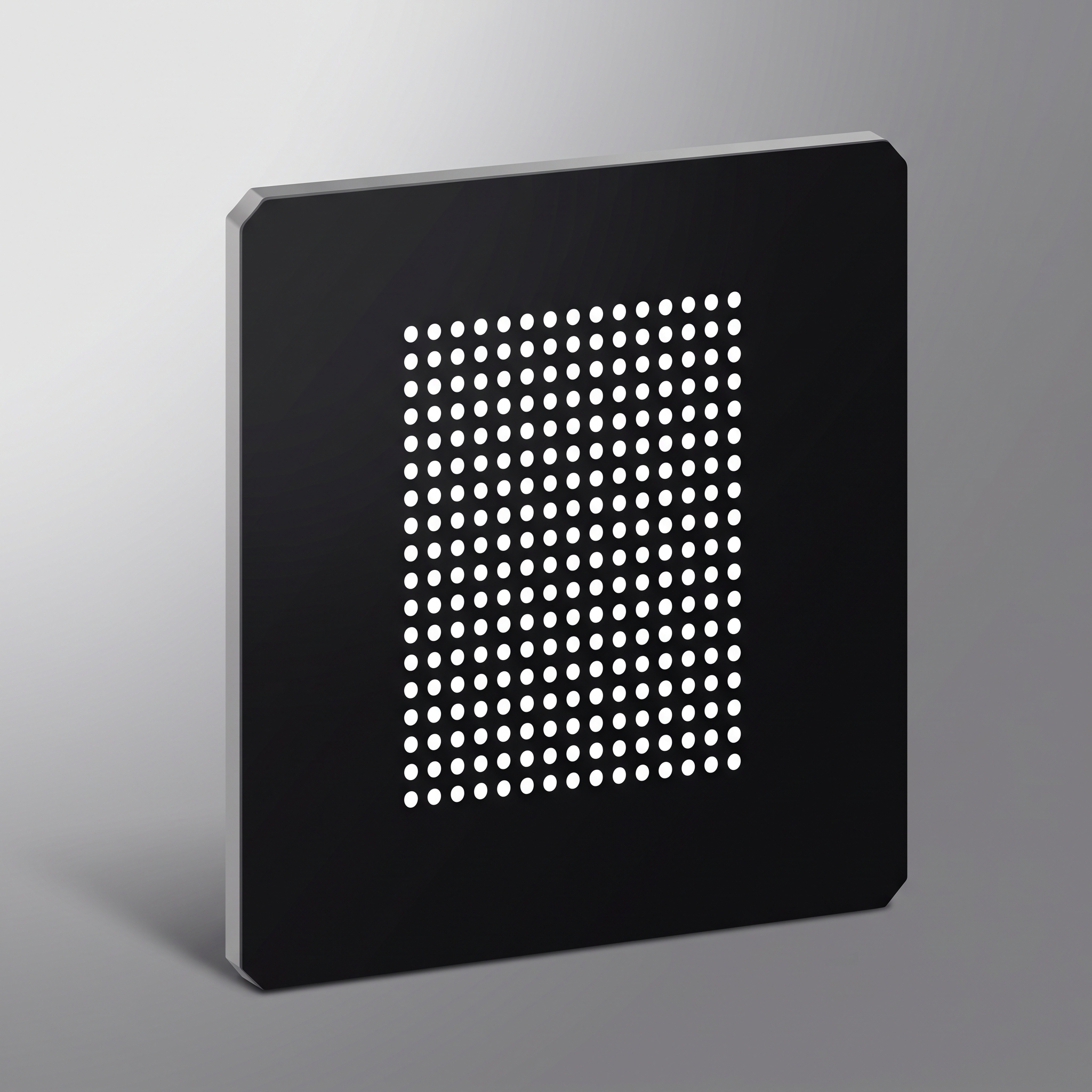
Negative-polarity circle-grid calibration targets with clear dots on an opaque field for transmitted-light machine vision and camera calibration.
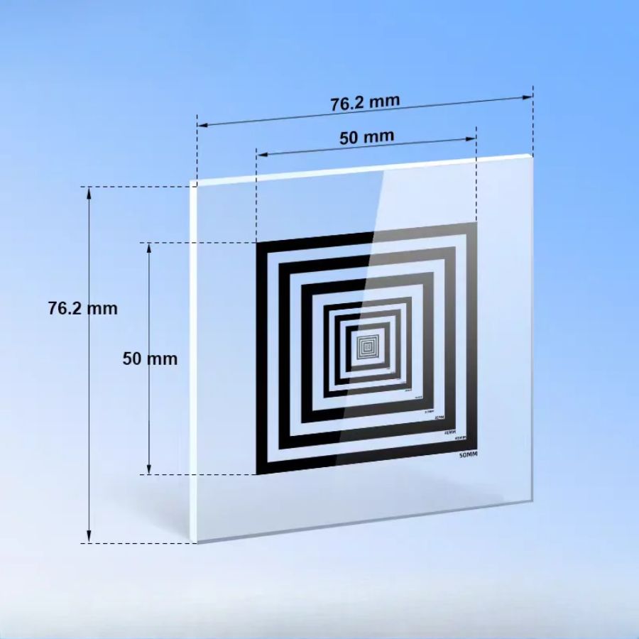
Nested-square glass targets for pixel-to-length calibration, centring, alignment and qualitative distortion checks. Define square sizes, gaps, line widths and measurement method.
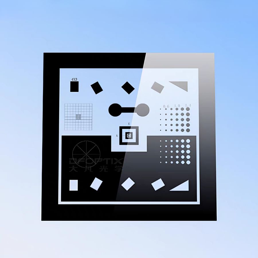
Combined imaging targets bring several reference geometries onto one substrate for multi-step focus, alignment, scale and image-quality workflows. Each region has its own measurement purpose.
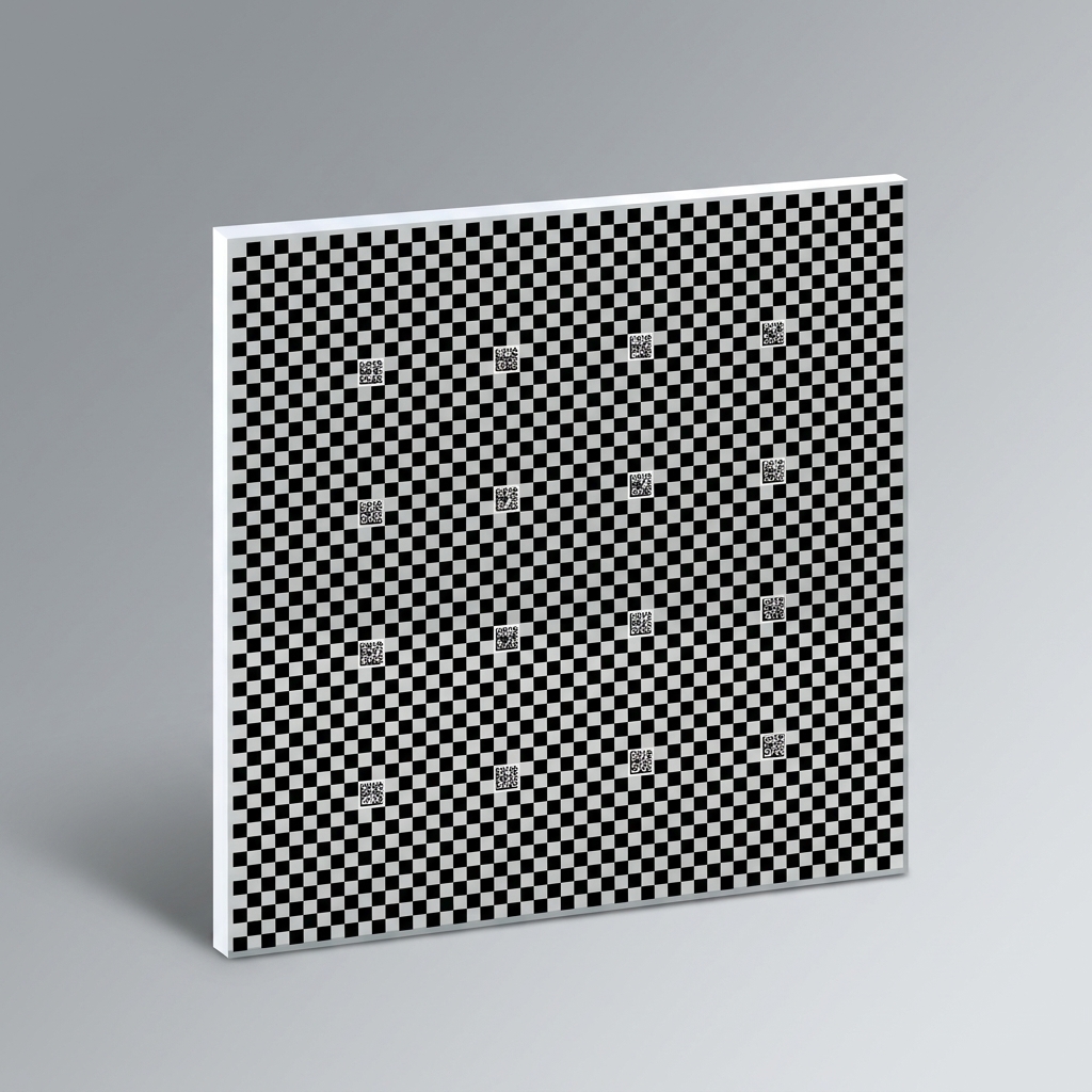
Data Matrix coded checkerboard calibration targets for camera distortion, stereo and multi-camera coordinate calibration. Specify code IDs, physical corner coordinates, substrate and pattern polarity.
| Product type | When to choose it |
|---|---|
| Checkerboard Calibration Targets | Choose it when the calibration software detects checkerboard corners and the imaging setup can resolve their intersections and surrounding border. It supports lens-distortion and camera-geometry estimation from suitable views. |
| Positive Checkerboard Calibration Targets | Choose square pitch and board dimensions from the working field of view. State square and inner-corner counts separately, then match material, pattern polarity and inspection criteria to the illumination and detector. |
| OpenCV Chessboard Calibration Targets | Specify square pitch, internal corner count, plate and active-field dimensions, substrate, polarity, viewing side and inspection tolerance. |
| Dot Array Calibration Targets | Choose a circle grid when your calibration pipeline uses circular features and can maintain consistent point ordering. Diameter, centre pitch and polarity are selected together to keep the dots distinct at the required magnification, focus and viewing angles. |
| HALCON-Compatible Calibration Targets | Specify the HALCON version, calibration-object model, dot diameter and pitch, point count, fiducials, substrate, polarity and matching description file. |
| HALCON Hexagonal Calibration Targets | Specify the HALCON version, mark diameter and spacing, finder positions, polarity, substrate, viewing side and matching .cpd file before manufacture. |
| Negative Checkerboard Calibration Targets | Specify square pitch, square count and internal-corner count, active field, substrate, pattern-side orientation and clear-square polarity. Confirm that the detector accepts the chosen contrast and coordinate order. |
| Negative Dot Array Calibration Targets | Specify dot diameter, centre pitch, row and column count, clear-dot polarity, substrate and pattern-side orientation. Confirm that the detector accepts the contrast polarity and coordinate order. |
| Concentric Square Test Targets | Choose this family when the result you need is a physical scale, a repeatable centre or a check of edge geometry. Use a checkerboard or dot array when software must solve a full intrinsic and distortion model, and use USAF, NBS or Siemens patterns when the question is optical resolution. |
| Multi-Feature Imaging Test Targets | Start with a list of measurement outputs, then assign one region and acceptance method to each. A clear circular feature may be an optical aperture or a geometric reference; a patterned film opening is not necessarily a hole drilled through the glass. |
| Data Matrix (DM Code) Calibration Targets | Define the active pattern size, checker pitch, marker IDs and positions, a physical coordinate list, viewing side, lighting and the detector used in the calibration software. |
Compare geometries for camera intrinsic and distortion calibration.
Choose chrome on transparent glass for backlit transmission. Define dark features on a clear field or clear features in an opaque field explicitly. For reflected-light use, specify the required surface/background reflectance and illumination geometry. Substrate flatness and thickness should match the working field and fixture.
Geometric calibration targets supply known feature coordinates for image-scale, alignment and camera-model estimation.
Match circles, checkerboards, grids or composite features to detection software. Use the actual pitch, point order and active area.
Geometry, pitch, rows and columns, point order, software, field and substrate.
No. Actual geometry and coordinate conventions must match the selected detector and calibration model.