
Data Matrix (DM Code) Calibration Targets
Data Matrix coded checkerboard calibration targets for camera distortion, stereo and multi-camera coordinate calibration. Specify code IDs, physical corner coordinates, substrate and pattern polarity.
Coded positions across the calibration field
This target combines a checkerboard with embedded Data Matrix (DM) codes. The checker corners provide image features, while decoded markers help the software identify their region and orientation. Calibration still requires a matching list of physical feature coordinates.
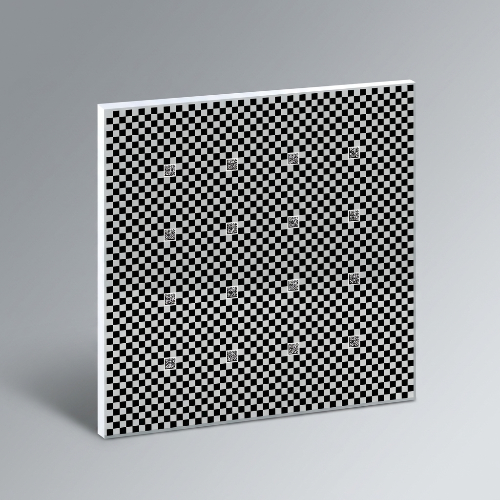
How DM code calibration works
The illustrated design is a hybrid target: many checkerboard corners cover the field, and multiple Data Matrix symbols provide identifiable regions. It is not a plain Data Matrix code used as a barcode, nor does every tiny black-and-white module automatically become a calibrated feature point. The selected detector determines which corners or marker features enter the calculation.
Capture the board in the intended working range, detect the chosen features, decode the identifiers where supported, and pair each image position with its approved physical coordinate. Camera intrinsics and distortion can then be estimated; stereo, hand–eye and multi-camera calibration also require the corresponding camera poses and image sets.
Where the coded pattern helps
Dense, traceable features
Checkerboard corners distribute measurements across the image. The DM symbols can label separate regions, helping software retain point identity when the board is partly outside the frame. Feature count depends on the actual detector and image quality.
Error correction has a defined role
ECC 200 Data Matrix uses Reed–Solomon error correction for code decoding. It may allow an identifier to be read despite limited local damage, but it does not restore a scratched corner or guarantee subpixel localisation.
Orientation and point order
The solid L-shaped finder and alternating clock tracks support symbol orientation. Unique, readable IDs can resolve board-region ambiguity when the calibration software uses them; the result still needs a consistent physical coordinate file.
Substrate follows the environment
Glass, ceramic, film and metal-backed formats can be discussed from the drawing. Flatness, expansion, reflectance and minimum feature size differ by material and process, so a value for one option must not be presented as a property of every board.
Applications
Camera and lens calibration
Use known target coordinates to estimate lens distortion, image scale and camera intrinsics for machine-vision measurement. A 3D profiler with an imaging camera may also use the pattern for its camera geometry; line-scan systems require a matching motion and acquisition procedure. Final dimensional accuracy depends on the complete imaging system, not the board alone.
Stereo and robot hand–eye systems
Shared point IDs and geometry help connect observations from two or more cameras. In eye-in-hand or eye-to-hand setups, acquire board poses that adequately constrain the camera-to-robot transformation used for picking, placement or assembly.
Electronics and semiconductor inspection
A compact, dense target can support optical calibration in AOI, PCB and wafer-inspection equipment. Choose a pitch that the actual magnification and sensor sampling can resolve reliably.
Large fields and camera arrays
Repeated coded regions can help identify overlapping portions of a larger board across cameras, including industrial photogrammetry setups. Coordinate alignment depends on the measured target geometry, shared observations and camera arrangement.
Technical specifications and material options
Supply the checker pitch, internal-corner count, active field, DM symbol size and IDs, marker-to-corner coordinates, pattern polarity, substrate outline and viewing side. Define the coordinate origin and point order in the same revision of the drawing and calibration file. We can discuss custom geometry from your drawing.
The figures below are options from the supplied material sheet, not one combined specification. Optical, thermal and dimensional values must be attached to the chosen substrate grade, coating, part size and test method. Film and aluminium were named as possible materials but no detailed values were supplied for them.
| Patterning process | Photolithography |
|---|---|
| Photolithographic line-width tolerance | ±0.2 µm |
| Substrate choices | Fused silica or soda-lime glass |
| Minimum feature width | 1 µm or 0.55 µm process options |
| Feature and overall placement accuracy | ±1 µm reference; define the measurement area and datum |
| Clear-area transmission at 550 nm | >95% reference, subject to glass grade and thickness |
| Thermal expansion, 20–200 °C | <5.0 × 10⁻⁷/K for the supplied fused-silica reference; not a soda-lime value |
| Expansion example | Approximately 0.6 µm per metre per °C for the quoted low-expansion option |
| Chrome finishes | Yellow chrome, low-reflection blue chrome or bright chrome |
| Quoted reflectance values | <13.4% at 550 nm; <1.8% at 650 nm; <2.67% at 750 nm. Match each value to the chosen coating. |
| Chrome optical density | Yellow chrome OD 3; blue chrome OD 5 |
| Chrome thickness | 120 ±5 nm (1200 ±50 Å) |
| Surface roughness | <0.025 µm reference |
| Flatness by measured length | <0.55 µm below 50 mm; <2 µm below 100 mm; <5 µm above 100 mm |
| Standard thickness options | 1, 1.6, 2.3 or 3 mm (supplied reference ±0.2 mm); 500 × 500 × 4.8 mm listed separately |
| Size range | 2 × 2 mm minimum; up to 800 × 960 mm (supplied reference ±0.1 mm) |
| Optional white backing | 40 µm smooth rear coating; 10 µm minimum feature for this option |
| Pattern polarity and outline | Opaque pattern on a clear field or clear pattern in an opaque field; square outline |
| Patterning process | Photolithography on the selected ceramic surface |
|---|---|
| Photolithographic line-width tolerance | ±0.2 µm |
| Substrate choices | Zirconia or alumina; grade-specific properties must be identified |
| Finish options | Matte chrome on matte ceramic or bright chrome on glossy ceramic |
| Minimum feature width | 4 µm matte option; 2 µm glossy option |
| Feature accuracy | ±2 µm reference for either finish |
| Outline accuracy | ±0.05 mm reference |
| Thickness choices | 1 mm (±0.1 mm), 2 mm or 3 mm (±0.1 mm) |
| Flatness by measured length | <30 µm below 100 mm; <60 µm below 200 mm |
| Size range | 2 × 2 to 228 × 228 mm; supplied outline tolerance ±0.1 mm |
| Chrome thickness | 120 ±5 nm (1200 ±50 Å) |
| Surface roughness | 0.2–0.7 µm supplied range; finish dependent |
| Matte chrome reflectance | <12.88% at 550 nm; <10.62% at 650 nm; <12.23% at 750 nm |
| Bright chrome reflectance | <9.56% at 550 nm; <1.89% at 650 nm; <11.168% at 750 nm |
| Quoted ceramic properties | Expansion <6.7 × 10⁻⁶/K (40–400 °C); density ≥3.66 g/cm³; hardness ≥80 HRA. Verify against the chosen grade. |
| Polarity and finishing | Opaque or clear pattern; square, elliptical or drawing-defined laser-cut outline, holes and chamfers |
| Optional protective film | Thin film over the chrome pattern, specified with optical and cleaning requirements |
Drawing, inspection and delivery
Before production, confirm the drawing revision and an explicit coordinate map: checkerboard corner positions, Data Matrix IDs, symbol orientation and any exclusions at the plate edge. For acceptance, measure the agreed feature positions and sizes, inspect clear/opaque defects, and check code readability under the specified illumination. A board measurement report is separate from the accuracy of the installed camera system.
For a quotation, send the usable area, substrate and thickness, working distance or field of view, lighting mode, target polarity, coordinate data and required inspection record. If the software expects a particular board model or file format, include that specification with the drawing.
Request a QuoteCommon questions
Is this the same as a QR-code target?
No. The identifiers shown are Data Matrix symbols. Data Matrix and QR Code are different code families, and calibration requires the correct detector and matching target coordinates.
Does ECC 200 make damaged corners accurate?
No. Error correction helps recover the encoded identifier. Damaged or blurred geometric features may still need to be rejected from the calibration calculation.
Can it calibrate a multi-camera rig?
Yes, when the cameras observe enough shared identified features in suitable poses and the physical coordinate map matches the target. The calibration method and image coverage determine the result.
Selection notes
This Data Matrix calibration target combines checkerboard corners with coded region identifiers. Geometry supplies image measurements; decoded IDs help establish region identity and orientation.
Pair detected image features with physical coordinates from the same artwork revision. ECC 200 Reed–Solomon correction concerns code decoding; it does not restore damaged corner geometry or guarantee subpixel accuracy.
Information for your inquiry
Square pitch and inner corners, DM payload and module size, marker coordinates and direction, coordinate file, detector, material and illumination.
Does each module inside a Data Matrix symbol automatically become a calibration point?
No. The detector and geometric model define which corners or other features enter calibration. Marker identity, image coordinates and physical coordinates must be linked explicitly.