
HALCON-compatible calibration targets
Circle-grid calibration plates made to a defined pattern and matching description file for HALCON camera-calibration workflows.
Discuss your drawingView technical specifications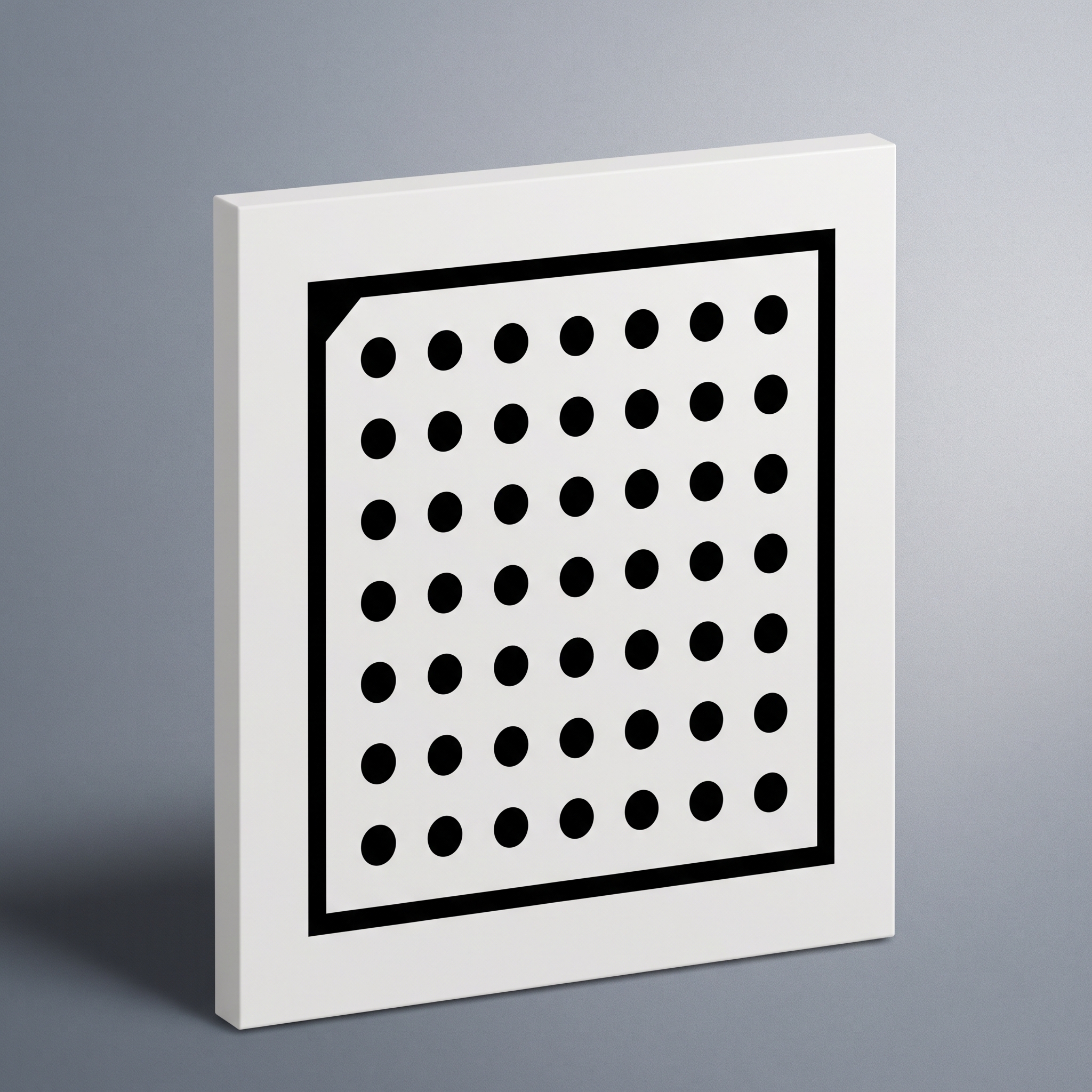
A known pattern for camera calibration
This target places circular features at defined physical coordinates. HALCON detects their image positions across multiple views and relates them to the target geometry to estimate camera parameters and pose. The plate geometry, image-acquisition conditions and matching calibration-object description all affect the result.
HALCON is software by MVTec. This is an independently made target specified for interoperability, not an MVTec-manufactured or endorsed product.
See other dot-array targetsHow calibration works
Detect the pattern
HALCON locates the calibration object and records observed image points. Contrast, focus, dot size and the fiducial must remain detectable at every intended pose.
Match physical coordinates
The calibration-object description supplies the physical geometry used to interpret the detected points. A file from a different plate or artwork revision is not interchangeable.
Solve and verify
After acquiring several useful views, calibrate_cameras estimates the selected camera model. Review residuals and validate the result against an independent measurement.
The usual data-model workflow uses create_calib_data, set_calib_data_cam_param, set_calib_data_calib_object, find_calib_object and calibrate_cameras. Select the operators and camera model for the installed HALCON version.
Pattern and description file
A circle grid is only useful to the software when its physical geometry and orientation can be matched to the digital model.
| Circle grid | Dot diameter, X/Y centre pitch, rows, columns and point coordinates |
|---|---|
| Orientation feature | Corner or fiducial geometry matched to the calibration-object model |
| Pattern polarity | Dark dots on a light field or clear dots on an opaque field, according to illumination |
| Description data | A .descr file matching the finished pattern, dimensions and revision |
| Substrate and outline | Glass, ceramic or film; drawing-defined outline and pattern side |
A regular grid needs a defined origin and row order. An asymmetric or hexagonal arrangement needs its own coordinate model and detector settings. A corner marker can break rotational ambiguity, but its shape and location must match the selected calibration-object description.
Dark dots on a light field suit reflected-light setups; clear dots on an opaque field suit transmitted light when the substrate itself passes light. A chrome opening on opaque ceramic does not become a transmissive aperture.
Circle grids and checkerboards
Both geometries can support subpixel image-point localisation. Choose the pattern that the intended HALCON workflow detects reliably under the actual lens, illumination and viewpoint.
| Consideration | Circle grid | Checkerboard |
|---|---|---|
| Reference feature | Circle centres | Internal corners |
| Matching detector | Circle-grid detection with the expected point order | Corner detection with the expected inner-corner count |
| Orientation | A matching fiducial or asymmetric layout can resolve point order | Board orientation and corner order must be established by the workflow |
| Image conditions | Dot boundaries, sampling and contrast affect centre estimation | Corner sharpness, sampling and contrast affect corner estimation |
At an oblique view a circle projects as an ellipse, and the measured ellipse centre can differ from the projection of the physical circle centre. Include camera angle and the chosen calibration model when assessing positional accuracy.
Technical specifications
Glass, ceramic and film configurations are listed in full below. Their figures describe different material and process options; use the approved drawing to define the selected combination.
Glass target
Fused silica or soda-lime glass with a photolithographic dot pattern.
| Substrate | Fused silica / soda-lime glass |
|---|---|
| Process | Photolithography |
| Line-width tolerance | ±0.2 µm |
| Minimum feature width | 0.55 µm or 1 µm, by pattern configuration |
| Feature and overall accuracy | ±1 µm |
| Clear-area transmission | >95% at 550 nm |
| Chrome finish | Yellow, low-reflection blue or bright chrome |
| Optical density | Yellow chrome OD 3; blue chrome OD 5 |
| Glass thickness | 1, 1.6, 2.3 or 3 mm (±0.2 mm) |
| Large-format glass thickness | 4.8 mm for the 500 × 500 mm format |
| Outline size | From 2 × 2 mm up to 800 × 960 mm |
| Outline tolerance at maximum format | ±0.1 mm at 800 × 960 mm |
| Fused-silica expansion | <5.0 × 10⁻⁷/K at 20–200°C |
| Low-reflection chrome reflectance | <13.4% at 550 nm; <1.8% at 650 nm; <2.67% at 750 nm |
| Surface flatness | <0.55 µm for lengths <50 mm; <2 µm for lengths <100 mm; <5 µm for lengths >100 mm |
| Chrome coating thickness | 120 ±5 nm (1200 ±50 Å) |
| Surface roughness | <0.025 µm |
| Optional white backing | 40 µm coating; 10 µm minimum feature width |
| Outline shape | Square |
| Pattern polarity | Opaque dots or clear dots |
Ceramic target
Opaque ceramic plates with matte or bright chrome patterns for reflective imaging.
Ceramic is opaque and used in reflected-light configurations. It cannot form a backlit clear-dot plate.
| Substrate | Zirconia or alumina ceramic |
|---|---|
| Process | Photolithography |
| Line-width tolerance | ±0.2 µm |
| Pattern options | Matte chrome on matte ceramic; bright chrome on glossy ceramic |
| Minimum feature width | 4 µm matte; 2 µm glossy |
| Feature accuracy | ±2 µm |
| Outline accuracy | ±0.05 mm |
| Ceramic thickness | 1 mm (±0.1 mm), 2 mm or 3 mm (±0.1 mm) |
| Outline size | From 2 × 2 mm up to 228 × 228 mm |
| Outline size tolerance | ±0.1 mm at minimum and maximum formats |
| Flatness | <30 µm below 100 mm; <60 µm below 200 mm |
| Chrome coating | Matte chrome or bright chrome |
| Chrome thickness | 120 ±5 nm (1200 ±50 Å) |
| Surface roughness | 0.2–0.7 µm |
| Thermal expansion | <6.7 × 10⁻⁶/K at 40–400°C |
| Matte chrome reflectance | <12.88% at 550 nm; <10.62% at 650 nm; <12.23% at 750 nm |
| Bright chrome reflectance | <9.56% at 550 nm; <1.89% at 650 nm; <11.168% at 750 nm |
| Density | ≥3.66 g/cm³ |
| Rockwell hardness | ≥80 HRA |
| Optional protection | Thin protective layer above the chrome pattern |
| Edge and hole options | Laser-cut outline, hole, chamfer or bevel |
| Pattern polarity | Opaque pattern or clear pattern |
| Finish and shape | Matte or glossy; square, elliptical or drawing-defined cutouts |
Photographic film target
A thin, lightweight format for larger patterns where mounting and ambient conditions are controlled.
| Process | Photographic-film lithography |
|---|---|
| Application | Transmitted-light or backlit functional testing |
| Minimum feature width | 10 or 30 µm |
| Feature accuracy | ±10 µm |
| Film thickness | 0.18 mm (±0.01 mm) |
| Temperature-related dimensional change | 10 µm per °C per metre |
| Environmental response | Film dimensions also respond to humidity; control temperature and relative humidity during coordinate measurement |
| Emulsion | Silver halide, approximately 2 µm |
| Clear-area transmission | >90% across 400–700 nm |
| Optical density | OD >4 in solid black; grayscale density can be specified |
| Maximum format | 0.71 × 0.81 m at 10 µm minimum width; 1.68 × 3.5 m at 30 µm |
| Maximum-format tolerance | ±0.1 mm for both maximum formats |
| Pattern and cutting | Black, grayscale or sinusoidal grayscale; straight, laser-cut or perforated outline |
Aluminium and carbon-fibre plate constructions may also be specified by drawing for reflective or large-format installations; their geometry and acceptance values must be stated for the selected construction.
Where it is used
Machine vision metrologyUse known target coordinates to estimate camera geometry before dimensional inspection or image-to-world measurement.
Robot guidance and hand-eye calibrationCombine target observations with recorded robot poses to establish the camera-to-robot relationship; the target alone does not determine it.
Multi-camera and stereo systemsUse observations from each camera to estimate their relative poses and support coordinate registration or image stitching.
Lens-distortion correctionDistribute detectable points across the working field to fit and check the chosen distortion model for wide-angle or telecentric imaging.
Define the plate and file together
Share the camera setup and pattern drawing before choosing pitch, size and substrate. A change to the dot positions or fiducial geometry means the matching description data must be updated as well.
GeometryDot diameter, pitch, point count, border and fiducial dimensions.
OpticsReflection or transmission, pattern polarity, working wavelength and viewing side.
DeliveryPattern revision, matching description data and agreed inspection record.
Common questions
What makes this target HALCON-compatible?
The physical dot grid, orientation marks and matching calibration-object description must agree with the HALCON model and the camera setup. The product image alone cannot establish compatibility.
Why does the .descr file have to match the plate?
It defines the physical calibration-object geometry used with the detected image points. A different pitch, marker layout or revision can produce a plausible but incorrect result.
Which HALCON operation detects the target?
find_calib_object detects the calibration object and stores observations in the calibration data model. calibrate_cameras then solves the camera parameters from suitable observations.
Are dots always more accurate than checkerboard corners?
No. Both can provide subpixel image locations under suitable conditions. Compare the actual target geometry, camera sampling, lighting and detector instead of assuming one pattern is always better.
Which substrate suits the illumination?
Glass or film can carry transmissive patterns for backlighting. Opaque ceramic is used with reflected light. Material choice also depends on format, mounting and coordinate stability.
Can the pattern be customised?
Yes. Dot geometry, fiducials, polarity, material and outline follow the approved drawing. Matching description data must be generated or verified for that final artwork.
Share your calibration setup
Send the drawing, camera field, HALCON version, preferred substrate and description-file requirements so the physical target and software model can be reviewed together.
Request a quoteRelated calibration targets
Dot array calibration targetsNegative dot array targetsCheckerboard calibration targetsSelection notes
HALCON-compatible calibration targets use a defined regular circle grid with border and orientation features matched to calibration-object data.
For the traditional gen_caltab workflow, match the actual dot geometry, border, orientation and .descr file. Do not substitute hexagonal create_caltab settings or diameter conventions.
Information for your inquiry
HALCON version and operator, grid dimensions, dot diameter and pitch, border, orientation marks and matching description data.
Does HALCON-compatible mean the board is made or endorsed by MVTec?
No. TL OPTIK is an independent manufacturer. HALCON names the intended software interoperability; the physical geometry and data must match the selected workflow.