Applications and compatible instruments
For image-scale checks, distortion evaluation, optical alignment and coordinate measurement in machine vision and microscopy.

Grid Calibration Target R2: For image-scale checks, distortion evaluation, optical alignment and coordinate measurement in machine vision and microscopy.
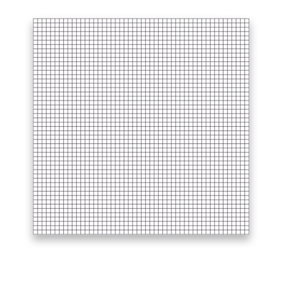
A grid target places known line intersections or square boundaries across an image field. It helps reveal geometric distortion, orientation and spacing differences while providing coordinates for a compatible calibration workflow.
Choose a grid to divide an observation field into known regions, compare spacing or support image-coordinate measurements. Use a counting chamber instead when a liquid volume must be defined.
A line grid makes spacing and field distortion visible over a broad area. Checkerboards and dot arrays provide features designed for their respective detection algorithms. Straight-looking grid lines alone do not establish a calibrated camera model.
Pattern size, feature spacing, polarity, usable field, substrate outline and mounting references can be selected around the camera and illumination. Measured geometry and traceable calibration are separate documentation requirements.
A glass target in the selected pattern, polarity and substrate format, with the dimensional inspection or calibration records included in the order.
For image-scale checks, distortion evaluation, optical alignment and coordinate measurement in machine vision and microscopy.
Inspect intersections, cumulative pitch, orthogonality, line quality and usable-area flatness.
Quality & Inspection PhotolithographyKnown feature positions for image scale and geometric calibration.
Specify the X/Y pitches, usable field and reference coordinate file. Target flatness and fixture alignment help prevent apparent distortion from the target itself.
Grid Calibration Target R2: For image-scale checks, distortion evaluation, optical alignment and coordinate measurement in machine vision and microscopy.
Match this artwork reference to its labelled dimensions, polarity and active field. The product image, manufacturing artwork and inspection drawing should identify the same revision.
Artwork reference, labelled geometry, active area, substrate outline, illumination and inspection requirements.
Use the pattern reference and its specific geometry, labels and intended measurement. A similar outline or photograph does not establish the same frequency, coordinates or reading convention.