
Transmissive vs Reflective Glass Linear Scales
Choose the optical path from the available machine space, readhead geometry and contrast measurement, then define pitch, datums and acceptance conditions.
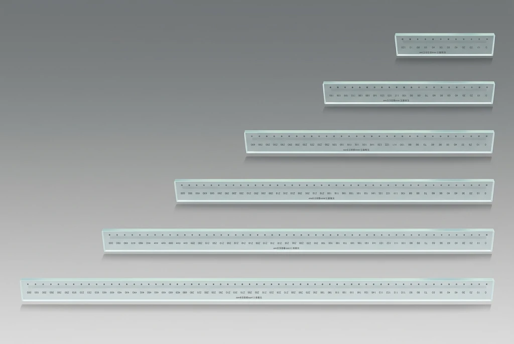
Choose the light path before choosing the pitch
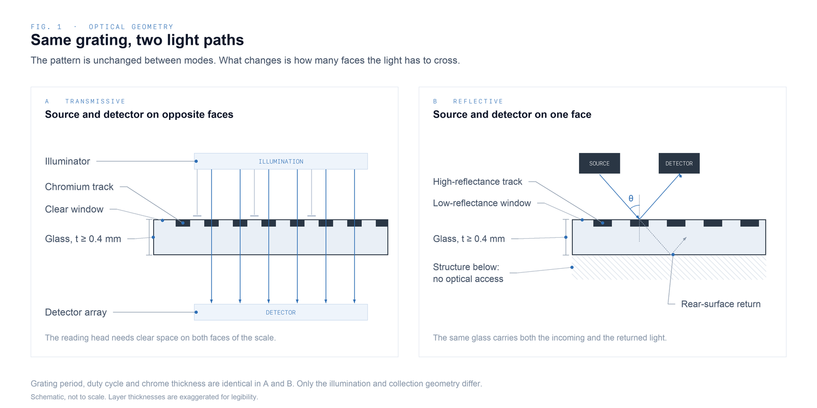
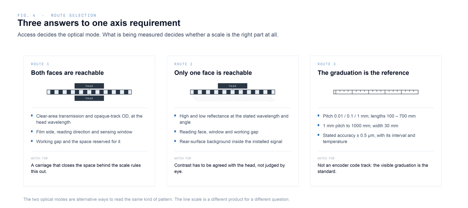
Use a transmissive scale when the source and detector can sit on opposite sides of the glass. Use a reflective scale when the complete readhead must remain on one side. Pitch does not decide this choice; the machine envelope and the readhead do.
| Question | Choose transmissive | Choose reflective |
|---|---|---|
| Available optical access | The source and detector can occupy opposite sides of the scale. | The readhead must illuminate and receive light from the same side. |
| Contrast to specify | Clear-area transmission and opaque-track optical density at the readhead wavelength. | High and low reflectance at the stated wavelength and incidence angle. |
| Typical mechanical reason | The carriage has clearance behind the glass and allows a through-beam path. | The carriage is enclosed or only one face of the scale is accessible. |
Do not treat “reflective” as another word for “absolute”, or “transmissive” as another word for “incremental”. Optical mode and encoding method are independent decisions.
The glass component carries the pattern; the complete system creates the position result
This guide compares patterned glass components used with optical readheads. The scale defines the pattern, optical contrast, outline and datums. Resolution, full-travel accuracy and repeatability also depend on the readhead, interpolation electronics, mounting, guideway and temperature.
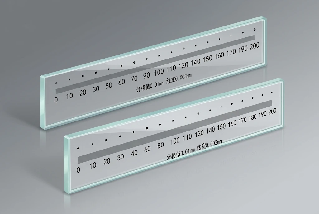
A high-precision glass line scale belongs to a different measurement route. Its visible graduation is read directly as a length reference for calibration or indication checks. It is not simply a third optical encoder mode.
The same patterned glass can require a different optical specification
In a transmissive arrangement, light passes through the substrate and pattern before reaching a detector on the opposite side. In a reflective arrangement, illumination and detection remain on the same side, so the film stack, incidence angle and unwanted rear-surface reflections affect the returned signal.
Specify the contrast pair the head actually reads
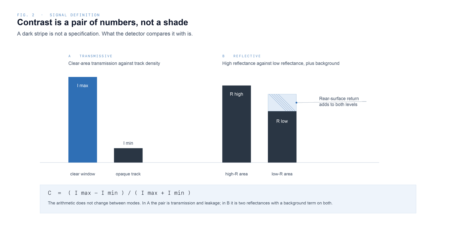
For a transmissive scale, record clear-area transmission and opaque-track optical density at the working wavelength. For a reflective scale, record both high and low reflectance at the working wavelength and incidence angle. A contrast value without its measurement conditions is incomplete.
Pitch determines the raw period, not the complete accuracy
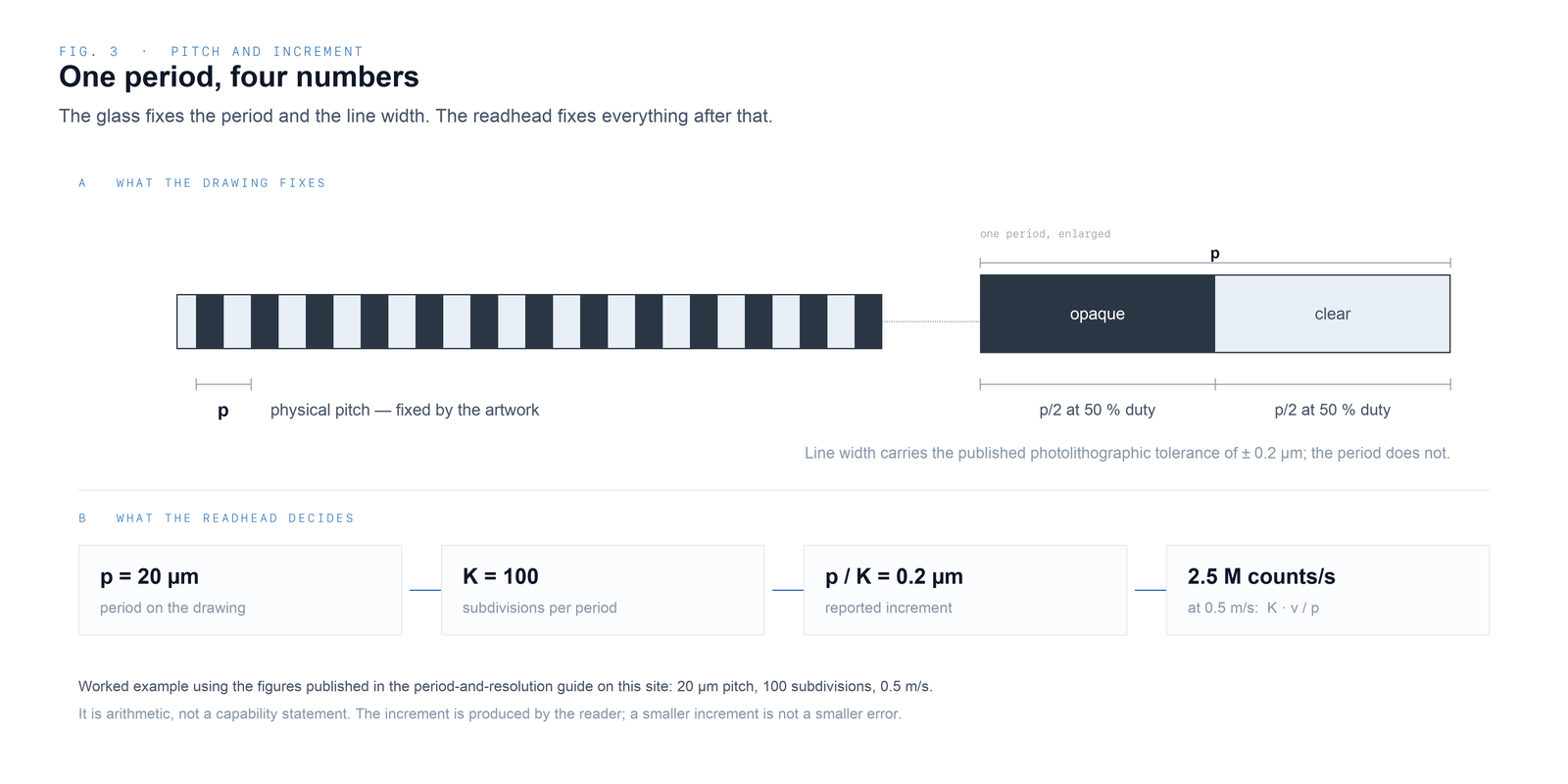
If the grating pitch is p and the electronics produces K stable subdivisions, the nominal output increment is p/K. This is a resolution calculation. It does not include pattern placement, mounting strain, readhead alignment, guideway error or thermal expansion.
Keep component limits separate from system performance
The values below summarize the published supply routes used for comparison. They do not replace an approved drawing. Material, active length, wavelength, optical contrast and the inspection plan must be confirmed for each order.
| Property | Transmissive scale | Reflective scale | High-precision line scale |
|---|---|---|---|
| What is read | Light passing through clear and opaque regions | Light returned by high- and low-reflectance regions | The visible graduation as a length reference |
| Optical access | Both faces | One face | Read by the measuring instrument |
| Substrate route | B270, K9 or soda-lime glass; fused silica on request | B270, K9 or soda-lime glass; fused silica on request | Optical glass according to the agreed schedule |
| Thickness / TTV / surface figure | ≥ 0.4 mm / ≤ 2 µm / λ/4 | ≥ 0.4 mm / ≤ 2 µm / λ/4 | Defined by the drawing |
| Photolithographic line-width tolerance | ±0.2 µm | ±0.2 µm | Line width follows the selected schedule |
| Mechanical cutting accuracy | ±0.02 mm | ±0.02 mm | ±0.02 mm |
| Pitch or length | By approved drawing | By approved drawing | 0.01 / 0.1 / 1 mm pitch; scheduled lengths depend on pitch |
| Accuracy boundary | System result; not a standalone scale guarantee | System result; not a standalone scale guarantee | ±0.5 µm only with the stated interval, temperature and method |
The ±0.2 µm value applies to photolithographic line width. It does not automatically define pitch error, accumulated interval error or complete encoder accuracy.
Put these decisions on one controlled drawing
- Mode and reading faceState transmissive or reflective, which face the head reads and the coated-face orientation.
- Wavelength and angleGive the working wavelength in nanometres; for reflective systems, also state incidence angle and collection geometry.
- Optical contrastSpecify transmission and optical density, or high and low reflectance, with tolerances and measurement conditions.
- Pattern definitionInclude pitch or the complete code map, duty cycle, line width, polarity, absolute zero if required and the controlling revision.
- Active and overall lengthDimension the readable travel, handling margins and mounting land separately.
- Datums and directionDefine the reference end, increasing direction, index position and how each is measured.
- Substrate and geometryState material, thickness, TTV, surface figure, outline, edge finish and mounting exclusions.
- Acceptance planName the measured items, sampling, methods, limits and whether results refer to the free or mounted part.
Record the conditions that make every measurement reproducible
Acceptance separates the two optical modes because their optical measurements differ even when the mechanical drawing is identical. A result close to a limit should include measurement uncertainty and the agreed decision rule.
| Item | Controlled by | Record |
|---|---|---|
| Pattern dimensions | Line width, pitch and duty cycle on the drawing | Nominal and measured critical dimensions at agreed locations |
| Outline geometry | Mechanical drawing and ±0.02 mm cutting accuracy | Length, width, thickness, datums and edge features |
| Registration | Pattern origin and track-to-datum position | Measured offset from the stated datum and the method used |
| Transmissive contrast | Transmission and optical density at the stated wavelength | Measured values, wavelength, aperture and instrument |
| Reflective contrast | High and low reflectance at the stated wavelength and angle | Both reflectance levels and the measurement geometry |
| Traceability | Drawing revision and lot identification | Method, instrument, inspected area and report format |
Record the incoming free-part condition before mounting. Clamping or bonding can change glass shape, optical gap and reflected return, so installed results should not be compared with an undocumented incoming state.
Questions to resolve before an order
Can a transmissive scale be replaced by a reflective scale?
Only after the readhead and optical layout are reviewed. Illumination, detector position and contrast measurement differ between the two modes, even when the chrome pattern is similar.
Does reflective mean absolute and transmissive mean incremental?
No. Optical mode and encoding method are independent choices. Either optical path can carry a periodic incremental grating or an absolute code pattern.
Is a finer pitch automatically more accurate?
No. Pitch and interpolation determine the reported increment. Accuracy over travel also depends on pattern placement, mounting, alignment, guideway error and temperature.
Which tolerance applies to line width?
The confirmed photolithographic line-width tolerance is ±0.2 µm. Outline cutting accuracy and accumulated interval error are separate requirements and must be specified independently.
Share the optical path and drawing
Share the optical mode, reading face, wavelength, contrast pair, pattern, active length, datums, substrate and acceptance plan. We can then review the component against the actual readhead and machine envelope.