
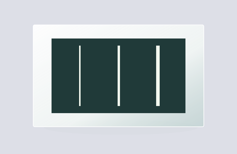
Optical Slits on Glass

Define a transmitted line with controlled edges.

Glass-supported slit openings for spectrometer entrance fields, light shaping and optical alignment.

Optical Slits on Glass

Product selection

What it is and what it does

A chrome-on-glass optical slit is a narrow transparent opening in an opaque film supported by glass. It defines a strip of admitted light for spectrometers, illumination shaping and optical alignment.

When to choose it

Choose a glass-supported slit when the optical system can accept the substrate in the beam path and needs a stable, precisely positioned opening. Select substrate transmission for the actual wavelength.

Product selection and delivery

How it differs from related products

The transparent slit passes light through intact glass. A metal foil slit has a physical opening with no glass beneath it. Their spectral transmission, reflections, mounting and handling requirements differ.

What can be customised

Slit width, length, number, spacing and orientation define the transmitted field. Film opacity, edge geometry and substrate thickness affect the light delivered to the instrument.

What you receive

A patterned glass slit component. The spectrometer housing, slit adjustment mechanism and detector are separate parts of the instrument assembly.

Specifications and inspection

Product configuration

Optical Slits on Glass
Slit geometryClear width, useful length and edge conditions
PlacementCentre, angle and mounting reference
Array relationshipsSpacing and crossings where applicable

Inspection requirements

Check width at defined positions along the slit, edge straightness, length and placement. Evaluate clear-window contamination and unwanted film pinholes separately.

Compare configurations
ConfigurationUseful forSelection detail
Single slitOne admitted strip of lightSpecify width and length separately
Multiple slitsRepeated channels or geometric referencesControl pitch and relative orientation
Metal through-slitA physically open beam pathDifferent substrate, support and spectral behaviour

Width and throughput are linked

In a spectrometer, narrowing the entrance slit can reduce the slit image width but also reduces admitted light. Spectral resolution still depends on dispersion, imaging aberrations, diffraction and detector sampling. A slit width alone cannot specify a wavelength resolution.

Length controls the perpendicular field

Slit length sets the accepted extent perpendicular to its width. Longer openings may admit more spatial information or light, but also expose off-axis aberrations and illumination non-uniformity. Match the length to the useful optical field.

The substrate is part of the optical path

Glass introduces wavelength-dependent transmission and surface reflections. Placing it in a converging beam can also alter the focus. Film-side location determines where the aperture plane lies relative to the mounting face.

Pattern and format options

Choose the functional geometry first, then define its size, orientation and mounting relationship.

Single optical slit

A single linear transmission window.

Crossed or repeated slits

Define intersection geometry or repeat spacing in the drawing.

Define the component and its inspection

Control itemInformation to confirm
Geometry and position
  • Slit width and length, measured independently
  • Edge straightness, spacing and position relative to mounting
  • Wavelength, film opacity and substrate transmission
Substrate and optical pathSpecify glass grade, thickness, wavelength and illumination side. Review transmission and reflections in the actual optical arrangement.
Inspection and acceptanceCheck width at defined positions along the slit, edge straightness, length and placement. Evaluate clear-window contamination and unwanted film pinholes separately.
Drawing and revisionProvide a 1:1 DWG with declared units, clear and opaque layers, viewing direction, active area and the approved revision.
Preparing your DWG drawing

Where this product is used

Common questions

Is the slit cut through the glass?

No. This product uses a transparent opening in the coating while retaining the glass support. A physical through-slot is a different construction.

Does a narrower slit always improve the measurement?

Only until other optical and sampling limits dominate. Reduced light can worsen noise or require longer integration.

Why specify the working wavelength?

Both clear-region transmission and blocked-region leakage depend on wavelength. Visible appearance does not establish UV or infrared performance.

Related products

Selection notes

Chrome-on-glass optical slits leave a narrow transmitting region in an opaque film to select an optical field or form a line of light.

Define slit width, length and location independently of glass thickness. Set the film face and mounting datums for the optical path.

Information for your inquiry

Slit width and length, straightness or position requirements, substrate, thickness, polarity and datums.

Is slit width the same as substrate thickness?

Slit width is the transparent width in the film plane. Substrate thickness is a separate glass dimension.

Selection and calibration guides

Search