
Pinhole Array Targets

Create a defined array of transmitted light points.

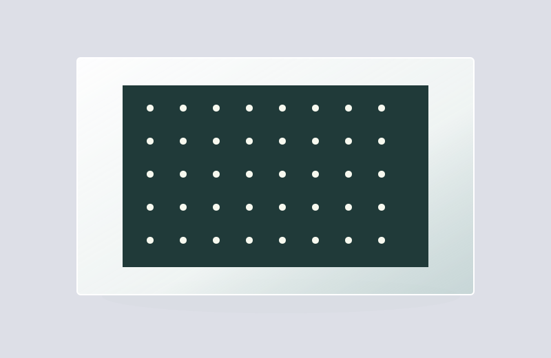
Repeated transparent circular openings for multi-point illumination, image registration and optical channel checks.

Pinhole Array Targets

Product selection

What it is and what it does

A chrome-on-glass pinhole is a small circular transparent region in an opaque film. It defines a compact light source or spatial selection point while the glass supports the pattern. Arrays repeat this geometry at specified locations.

When to choose it

Choose a single pinhole for a local optical reference or spatial filtering arrangement compatible with glass. Choose an array when several reference points, channels or repeated image locations are needed.

Product selection and delivery

How it differs from related products

A clear pinhole transmits light within a blocked field; a dark dot blocks light within a clear field. A glass-supported pinhole also differs from a drilled or electroformed metal aperture because the substrate remains in the optical path.

What can be customised

Clear diameter, circularity, surrounding opaque area, array pitch and fiducials define the pattern. Substrate transmission and film optical density must be considered at the illumination wavelength.

What you receive

A glass-supported aperture or aperture array with defined clear regions. The physical support stays continuous beneath the openings in the film.

Specifications and inspection

Product configuration

Pinhole Array Targets
Aperture diameterClear-circle diameter at the patterned film
Array geometryPitch, rows, columns and coordinate origin
Imaging conditionsWavelength, magnification and sampling

Inspection requirements

Measure aperture diameter and circularity separately from centre placement and array pitch. Check unwanted clear defects outside the designed aperture.

Compare configurations
ConfigurationUseful forSelection detail
Single clear apertureOne local optical referenceDiameter and location serve different functions
Clear aperture arrayMultiple transmitted reference pointsDefine centre positions independently of diameter
Dark-dot arrayOpaque features in a clear fieldOpposite polarity; adapt illumination and detection

A smaller opening changes both light and diffraction

Reducing the diameter reduces admitted light and changes the diffracted field. The useful diameter depends on wavelength, numerical aperture and the role of the pinhole in the system. It cannot be selected from a desired image spot size alone.

Clear apertures and dark dots are opposite geometries

A camera-calibration algorithm configured for dark circles may not detect bright apertures without adapting the detector and lighting. Define the transmitted image and the surrounding field explicitly before choosing polarity.

Separate diameter from array placement

An array can have uniform diameters but incorrect centre positions, or correct centres with variable diameters. Position controls geometric relationships; diameter and edge quality influence transmitted light and feature detection.

Pattern and format options

Choose the functional geometry first, then define its size, orientation and mounting relationship.

Regular pinhole array

Repeated bright apertures with a defined pitch.

Custom coordinate array

A non-uniform arrangement defined by the measurement task.

Define the component and its inspection

Control itemInformation to confirm
Geometry and position
  • Clear diameter, circularity and opaque surround
  • Single aperture or array coordinates and fiducials
  • Substrate, wavelength, film side and illumination
Substrate and optical pathSpecify glass grade, thickness, wavelength and illumination side. Review transmission and reflections in the actual optical arrangement.
Inspection and acceptanceMeasure aperture diameter and circularity separately from centre placement and array pitch. Check unwanted clear defects outside the designed aperture.
Drawing and revisionProvide a 1:1 DWG with declared units, clear and opaque layers, viewing direction, active area and the approved revision.
Preparing your DWG drawing

Where this product is used

Common questions

Is there a physical hole beneath a clear pinhole?

No. The opening is in the film; light continues through the glass substrate.

Can a pinhole array serve as a camera target?

Yes, if the illumination, coordinate geometry and feature detector are compatible. Bright apertures and dark dots may need different detection settings.

Is visible opacity enough for a laser application?

No. Wavelength, power density and exposure conditions affect suitability. Aperture geometry by itself establishes neither damage threshold nor laser-power handling.

Related products

Selection notes

Pinhole array targets place transmitting circular apertures at known coordinates in an opaque film on glass.

Specify diameter, pitch, row geometry and origin together; match the array to illumination and image sampling.

Information for your inquiry

Diameter, centre spacing, rows and columns, origin, polarity, substrate and active area.

Do the optical pinholes pass gas or liquid?

The transparent film openings still have glass underneath. Physical flow-through holes must be specified separately.

Selection and calibration guides

Search