What the component does
A patterned glass component may define a slit, aperture, coordinate field or alignment reference. Choose its optical job before choosing the pattern shape.

Place a defined aperture, slit or reference pattern in the optical plane where it performs a useful measurement or alignment function.
The illustrated plane is an example. A field stop and a pupil aperture belong to different conjugate relationships.
The clear slit highlights the active geometry; polarity and transmission are specified for the actual instrument.
A patterned glass component may define a slit, aperture, coordinate field or alignment reference. Choose its optical job before choosing the pattern shape.
Pattern location and mounting references connect the manufactured geometry to the optical axis. The clear aperture and coating should suit the beam and wavelength.
A precisely made pattern in the wrong optical plane can clip the wrong rays or create unwanted diffraction. Geometry alone does not define instrument performance.

Narrow transmitted-light regions on a glass support.
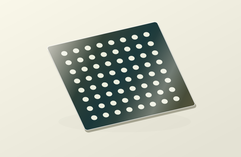
Defined circular clear apertures in an opaque coating.

Supplies a visible registration reference tied to the instrument mounting datum.

Projected lines, crosses or custom reference shapes in a compatible optical instrument.
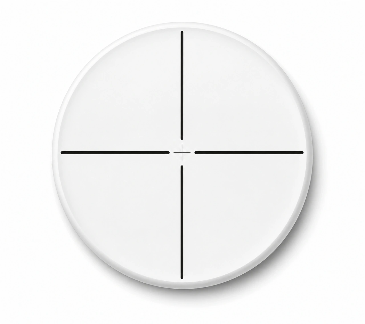
Reference centres for viewing and optical alignment.
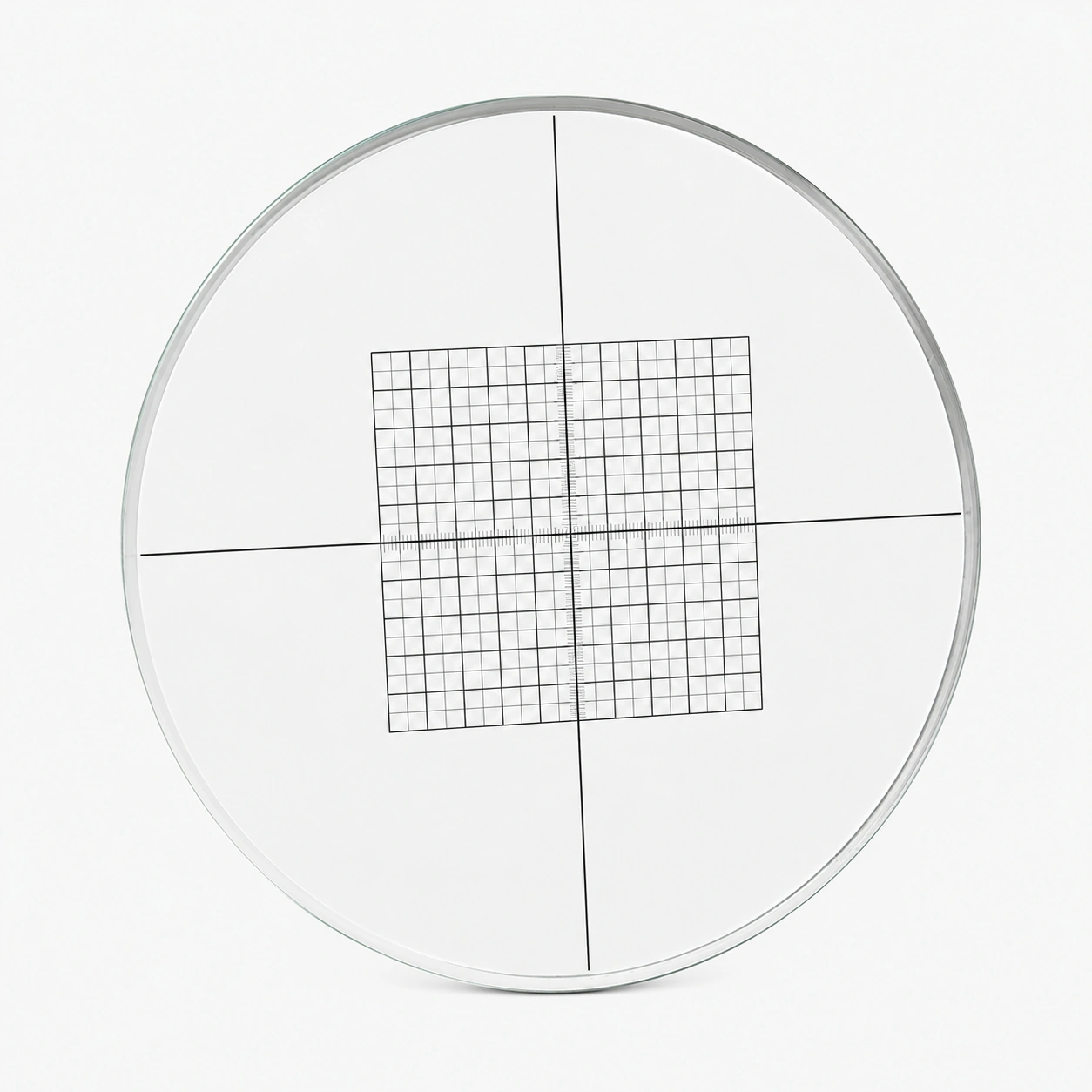
Instrument-integrated coordinate and alignment references.
Compare slits, circular windows and point arrays.
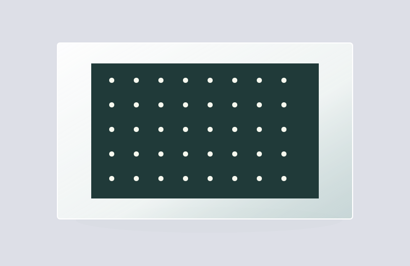
Bright-point arrays for compatible imaging and alignment tests.

Periodic amplitude patterns for an optical instrument design.
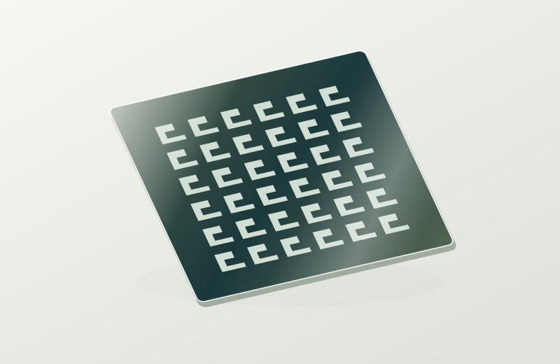
Custom functional artwork combining several feature types.
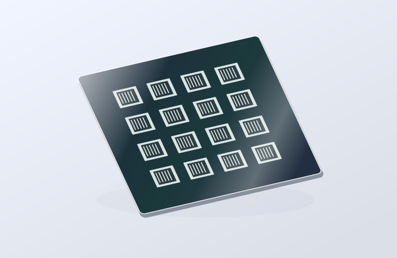
Approved masters for repeat pattern transfer.
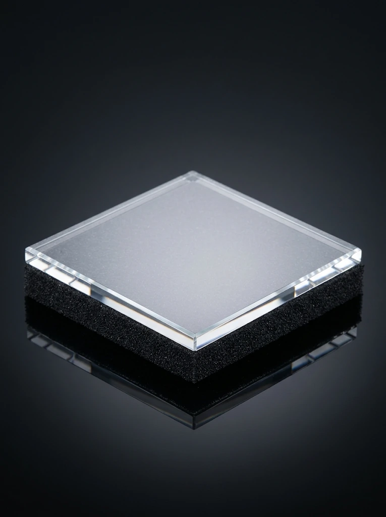
Uncoated glass prepared for coating or optical patterning.

A narrow transmitted line for selecting the instrument field or forming an alignment reference.
A compact transmitted point for checking alignment and optical channel position.
Patterned glass can establish a viewing reference, define a clear window in an opaque field or provide a periodic optical pattern. Examples include instrument crosshairs, alignment grids, glass-supported slits and spatial-reference arrays. The geometry is specified around the optical path and mechanical mounting.
Determine whether the glass is observed, illuminated in transmission or used in reflection. A transparent aperture in a chromium film still has glass beneath it. For small apertures and gratings, account for diffraction and substrate transmission rather than selecting only the mechanical dimensions.
A custom instrument may need an alignment centre, a narrow viewing window or a grid that identifies repeat observation positions. These are distinct functions that can share a patterned-glass manufacturing route. Define the optical role first, then combine only the features the instrument needs.
Crosshairs establish centres and directions; glass slits and pinholes define transmitted regions. The aperture plane is the patterned film surface, not automatically the nearest mounting face. Review film-side position, substrate thickness and the instrument focal plane together.
Patterned glass in custom instruments can provide centres, directions, transmitting windows and periodic references.
Crosshairs, grids, slits and pinholes perform different optical jobs. Define the functional plane and optical path before specifying geometry.
A chromium-film aperture transmits through glass underneath. A physical through-hole is a different structure and must be specified separately.