
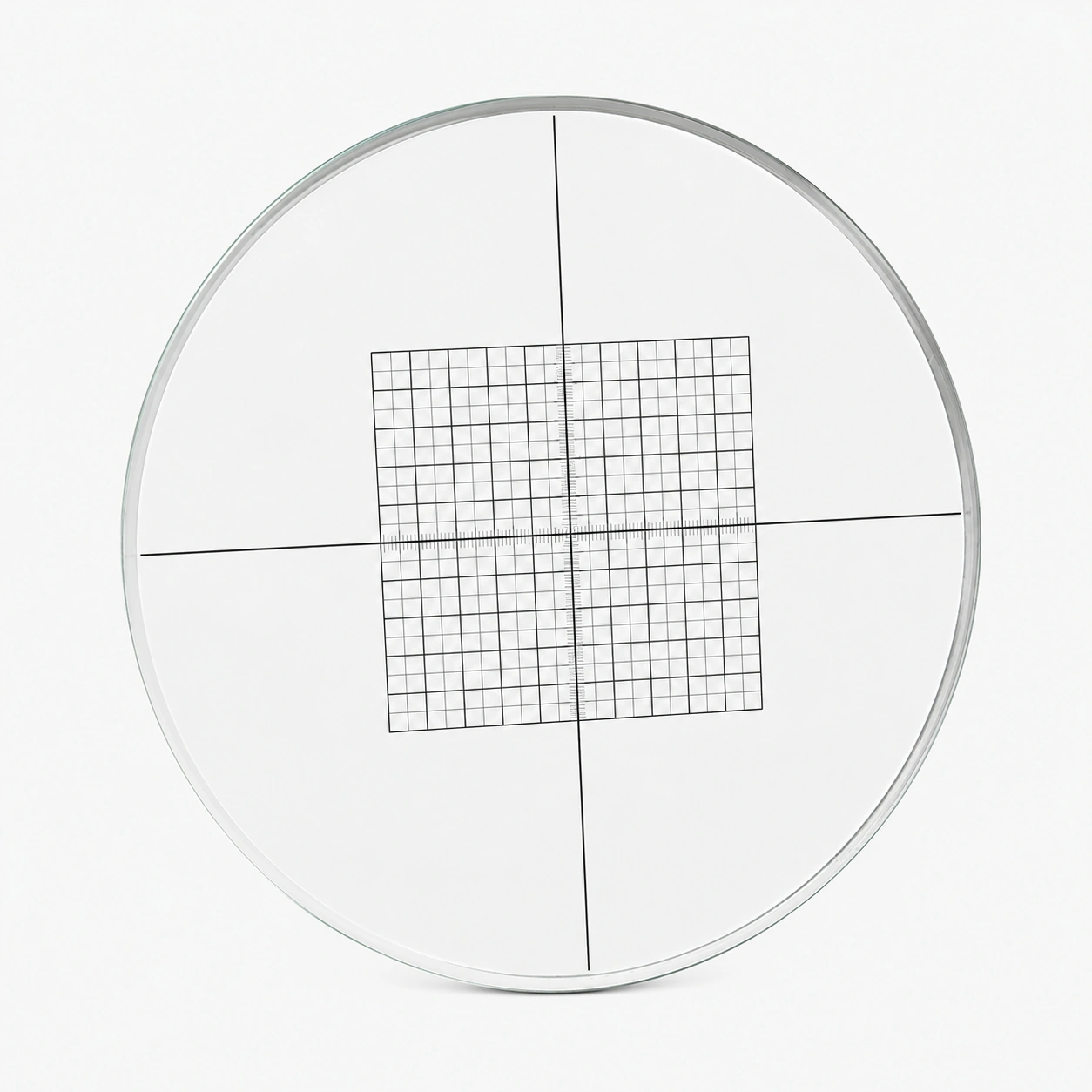
Precision Grid Reticles

Intersecting lines form known reference intersections across the field. Pitch, line width and orthogonality control the geometry used by the imaging system.

Precision Grid Reticles

Configuration and materials

Specify optical glass or fused silica, overall dimensions, thickness, pattern-side orientation and the clear aperture. Define transmission, reflectance or optical density at the working wavelength when optical contrast is critical.

  • Active field, scale or feature geometry and optical-plane location
  • Material, outside dimensions, thickness and mounting datums
  • Working instrument, illumination and viewing side
  • Critical tolerances, inspection intervals and reporting needs

From the pattern to a measurement

A coordinate reference inside the view

Grid intersections provide repeatable locations for comparing spacing, alignment and image geometry. In an eyepiece, specimen dimensions require calibration; an external calibration grid instead sits in the object scene.

Calibrate eyepiece divisions against a stage scale
Control both spacing and squareness

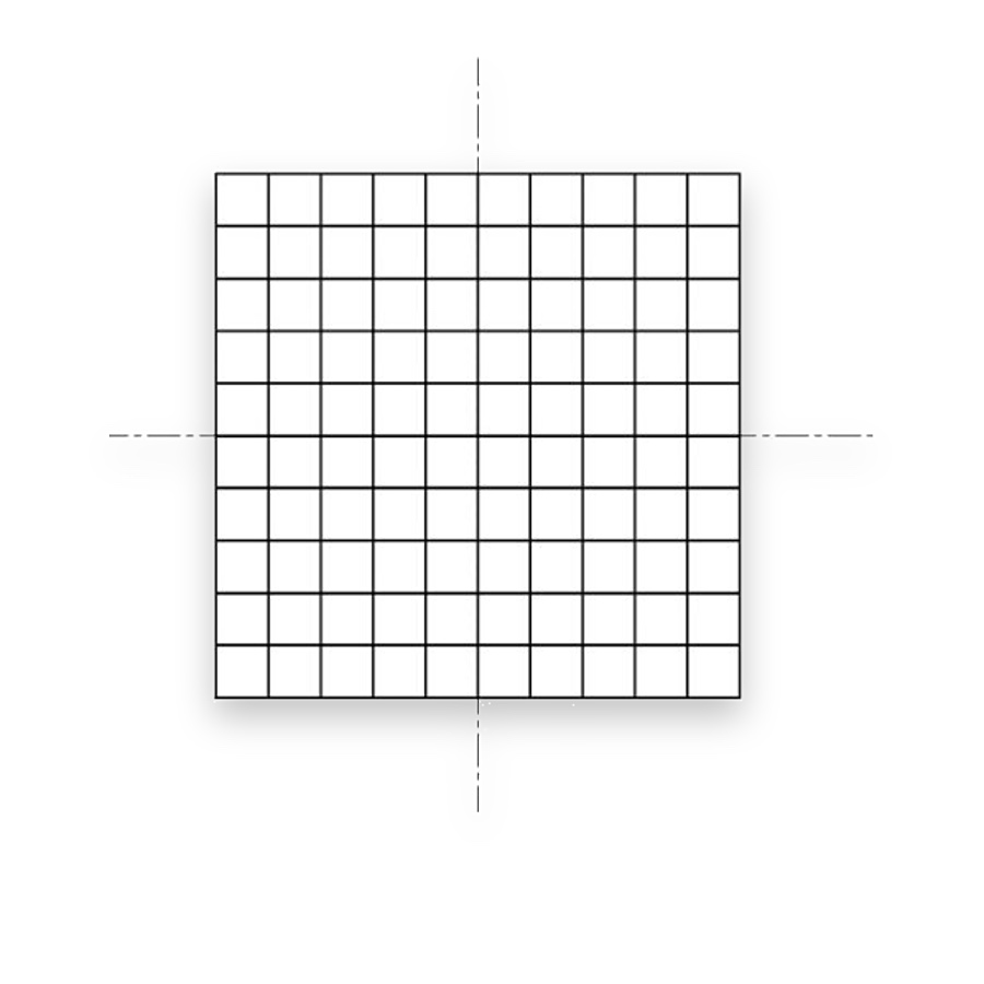
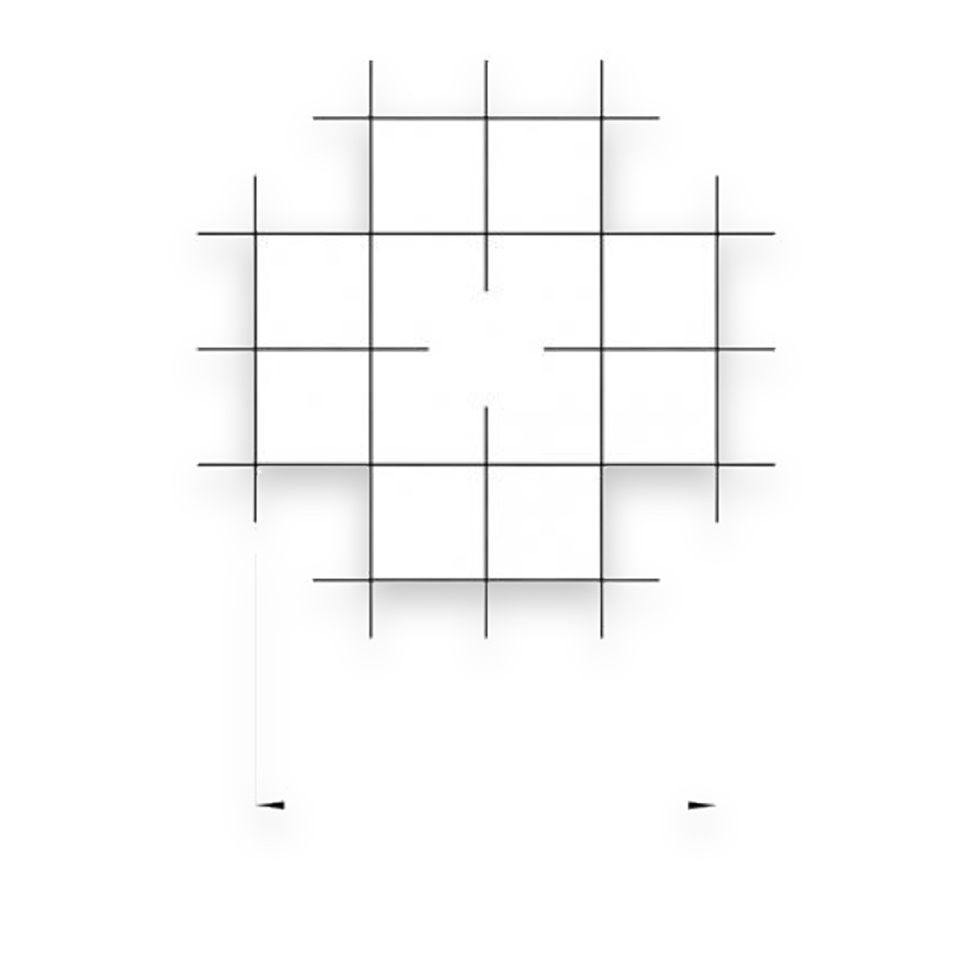
Specify X/Y pitch, orthogonality, cumulative spacing and the grid origin relative to the mounting datum. Equal nominal cell size does not establish coordinate accuracy over the full field.

Separate line width, pitch and placement tolerances

Choose by function

What it is and what it does

Intersecting lines form known reference intersections across the field. Pitch, line width and orthogonality control the geometry used by the imaging system.

When to choose it

Choose a grid to divide an observation field into known regions, compare spacing or support image-coordinate measurements. Use a counting chamber instead when a liquid volume must be defined.

How it differs from related products

An eyepiece grid is an internal coordinate reference; an external grid target is imaged at the object plane. A counting grid additionally follows a sampling rule. Pitch and orthogonality support geometric measurement, while chamber depth is relevant only to volume counting.

What can be customised

X/Y pitch, grid extent, line width, orthogonality, origin, numbering and placement relative to the mounting datum can be defined independently.

What you receive

A patterned glass reference component with the selected graduations, outline and mounting dimensions, accompanied by the specified inspection records.

Where this product is used

Pattern and format options

Precision Grid Reticles — Central grid with crosshairs

Central grid with crosshairs

Precision Grid Reticles — Pattern 070

Pattern 070

Precision Grid Reticles — G48

G48

Related pattern choices

Selection notes

Precision grid reticles provide line intersections, spacing and orthogonal directions as optical coordinate references.

Choose pitch, line width, usable area and origin. Add labels or locating marks when repeated positioning is required.

Information for your inquiry

X/Y pitch, line width, grid count, active area, orthogonal axes, origin and mounting outline.

How does a precision grid differ from a counting grid?

A precision grid emphasises geometry and coordinates. A counting grid must also match the sampling area and boundary rules of the counting method.

Search