
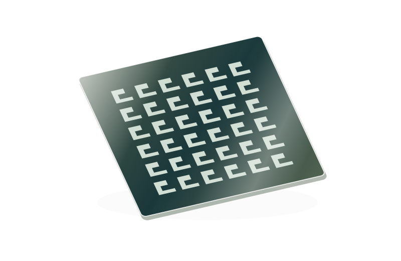
Chrome Patterned Glass

Several optical functions on one glass component.

Custom chromium features on flat glass create functional optical patterns for sensing, inspection and instrumentation. The geometry follows your artwork.

Chrome Patterned Glass

Product selection

What it is and what it does

Custom opaque chromium features and transparent areas turn flat glass into an optical component. A single drawing may combine lines, apertures, reference marks and identification. The film pattern and substrate geometry are controlled as separate features.

When to choose it

Use this route for a pattern that does not fit a standard product family. Describe what the pattern does in the instrument so critical features can be identified.

Product selection and delivery

How it differs from related products

This route combines optical features that do not fit one standard reticle or target layout. A photomask is used to transfer a pattern; functional patterned glass usually remains in the finished instrument.

What can be customised

Combine transparent windows, opaque regions, periodic lines, identification and datum marks. Substrate shape, thickness, coating side and useful optical field are independent choices within the instrument design.

What you receive

A patterned glass component with the agreed coating geometry, substrate outline and inspection records.

Specifications and inspection

Product configuration

Chrome Patterned Glass
Functional regionsClear windows, opaque patterns and reference marks
Pattern datumFeature coordinates relative to the mounting reference
Optical modeTransmission or reflection at the specified wavelength

Inspection requirements

Inspect the agreed critical dimensions, registration and clear/opaque defects against the approved drawing revision.

Combine the pattern around the optical task

Opaque film and clear regions can form lines, windows, scales and location marks on the same substrate. This is useful when a standard reticle or target does not include the required combination. Define which areas transmit light, which block it and which serve only as identifiers.

Relate each feature to the instrument

A window may define a viewing field while nearby fiducials locate that field for a camera. Their relative position may matter more than the overall plate size. Specify the functional relationships and mounting datum so that separate features can be inspected as one component.

Distinguish film patterning from glass machining

A clear region in chromium leaves the glass beneath it intact. Steps, cavities or physical through-holes require a separate machining route. State whether the component works in transmission or reflection, because opacity alone does not establish reflected contrast.

Pattern and format options

Choose the functional geometry first, then define its size, orientation and mounting relationship.

Combined windows and fiducials

Define the viewing area and its location in one pattern.

Lines, scales and identification

Separate measured features from non-functional labels.

Define the component and its inspection

Control itemInformation to confirm
Geometry and position
  • Artwork and minimum features
  • Pattern position on the substrate
  • Optical contrast and acceptance criteria
Substrate and optical pathSpecify glass grade, thickness, wavelength and illumination side. Review transmission and reflections in the actual optical arrangement.
Inspection and acceptanceInspect the agreed critical dimensions, registration and clear/opaque defects against the approved drawing revision.
Drawing and revisionProvide a 1:1 DWG with declared units, clear and opaque layers, viewing direction, active area and the approved revision.
Preparing your DWG drawing

Where this product is used

Common questions

Can several functional patterns share one component?

Yes. Supply one coordinate system and identify the critical relationship between the patterns and the mechanical outline.

Related products

Selection notes

Chrome-patterned glass uses drawing-defined transparent and opaque structures as functional patterns in optical instruments.

Define the pattern, polarity, physical outline and mounting datums together. The optical aperture remains supported by glass unless a mechanical opening is specified.

Information for your inquiry

Artwork, dimensions, substrate, thickness, film side, polarity and inspection datums.

Do I need both artwork and a mechanical drawing?

Artwork defines the functional geometry; the mechanical drawing defines outline, thickness and location. Together they define the component.

Search