What the component does
Crosshairs, rings and angular graduations provide references in surveying optics, alignment instruments and optical sights, including air-rifle scopes.

Give the observer a stable reference for comparing a target image with the instrument line of sight.
This simplified sighting telescope shows an image-plane reticle. Actual instruments may use different relay optics and focal-plane arrangements.
The offset is illustrative and is not a ballistic correction or a calibrated angular value.
Crosshairs, rings and angular graduations provide references in surveying optics, alignment instruments and optical sights, including air-rifle scopes.
The line width must remain visible without obscuring the observed feature. Reticle mounting and focal-plane placement determine how the reference relates to the scene.
A mismatch between the reticle and target image planes can create parallax. An angular scale also depends on the optical design and cannot be inferred from the glass pattern alone.
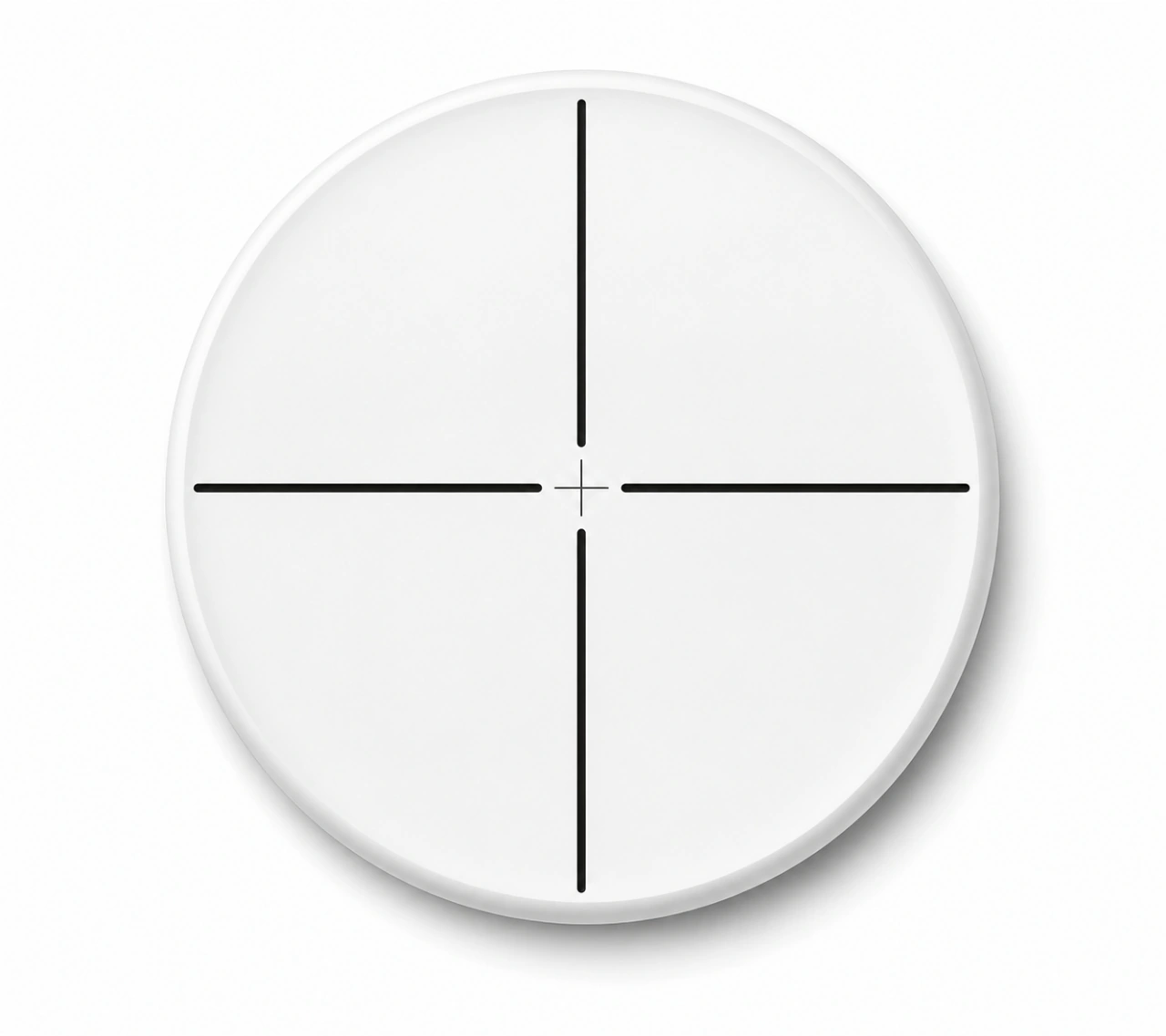
Centre and direction reference for aiming and optical alignment.
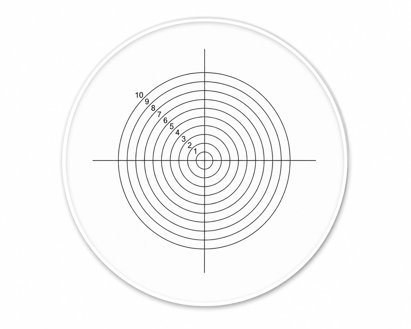
Compare round features and concentricity in a viewing field.
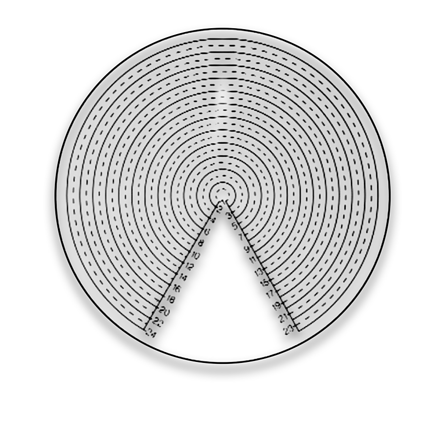
Angular graduation reference around a defined centre.
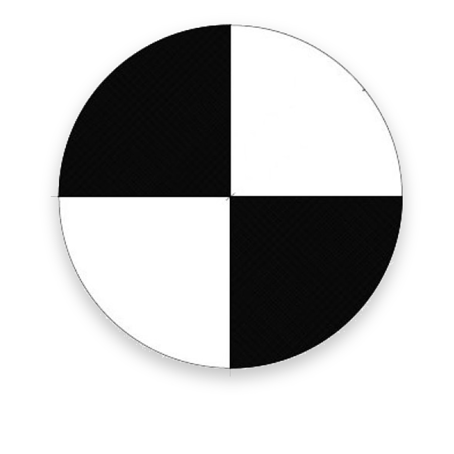
Orthogonal contrast boundaries for centre and orientation checks.
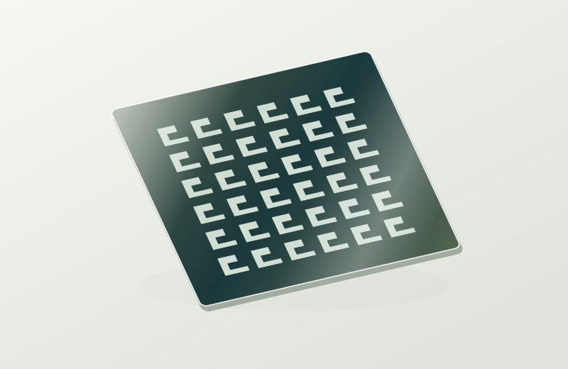
Drawing-defined glass reticles for the viewing reference required by an optical instrument.
An optical instrument often needs a visible datum alongside the target image. A reticle supplies that reference so an observer can compare target position, orientation or centring. Depending on the instrument, it may be viewed directly in an eyepiece or imaged by a camera.
Start with the observed feature: a point or intersection favours a crosshair, circular parts may benefit from concentric rings, and direction comparisons may use angular graduations. Line visibility, centre obscuration and focal-plane placement influence usability.
A glass reticle places a visible reference within a sighting optical system. Airgun scopes and other telescopic sights may use patterned glass for crosshairs or other specified viewing references. TL OPTIK supplies the patterned optical component to the instrument drawing; its focal-plane location, mounting and optical compatibility are defined by the sight manufacturer.
An interrupted centre can keep small target detail visible, while a continuous cross gives an obvious intersection. Opaque and clear pattern regions interact with illumination and the viewing background. Select the visible geometry before specifying decorative or redundant marks.
A reference that appears sharp but moves relative to the target as the viewing position changes may indicate an optical-plane mismatch. The reticle centre also needs a defined relationship to the mount. These checks connect pattern manufacture with instrument alignment.
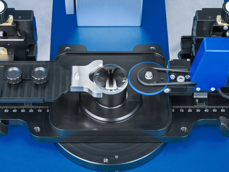
Optical assembly also requires a consistent relationship between the lens, mechanical axis and viewing reference. Reticles provide visible centre or direction references within a compatible instrument, while the assembly equipment establishes and checks the required positioning.
Aiming and alignment reticles provide visible centres and direction references.
Match the pattern to the viewing task and its optical plane to the target image. Check focus and parallax in the intended instrument geometry.
Relative motion as eye position changes may indicate a mismatch between the reticle and target image planes. Check alignment at the specified target distance.