Optical Pinhole Patterns on Glass

A chrome-on-glass pinhole is a small circular transparent region in an opaque film. It defines a compact light source or spatial selection point while the glass supports the pattern. Arrays repeat this geometry at specified locations.

Optical Pinhole Patterns on Glass

Configuration and materials

Specify optical glass or fused silica, overall dimensions, thickness, pattern-side orientation and the clear aperture. Define transmission, reflectance or optical density at the working wavelength when optical contrast is critical.

  • Clear diameter, circularity and opaque surround
  • Single aperture or array coordinates and fiducials
  • Substrate, wavelength, film side and illumination

Optical function of the opening

A small clear window on glass

A pinhole pattern creates a small transmitted reference in an opaque film. It can serve as a point-like source or alignment feature in compatible optics, with the glass retained beneath the opening.

Optical references in measuring instruments
Size the opening for the optical task

Diameter, circularity and centre position are component quantities. Whether the opening behaves as a point source depends on its size relative to the system’s imaging resolution and wavelength.

Check alignment in the complete instrument

Choose by function

What it is and what it does

A chrome-on-glass pinhole is a small circular transparent region in an opaque film. It defines a compact light source or spatial selection point while the glass supports the pattern. Arrays repeat this geometry at specified locations.

When to choose it

Choose a single pinhole for a local optical reference or spatial filtering arrangement compatible with glass. Choose an array when several reference points, channels or repeated image locations are needed.

How it differs from related products

A clear pinhole transmits light within a blocked field; a dark dot blocks light within a clear field. A glass-supported pinhole also differs from a drilled or electroformed metal aperture because the substrate remains in the optical path.

What can be customised

Clear diameter, circularity, surrounding opaque area, array pitch and fiducials define the pattern. Substrate transmission and film optical density must be considered at the illumination wavelength.

What you receive

A glass-supported aperture or aperture array with defined clear regions. The physical support stays continuous beneath the openings in the film.

Where this product is used

Pattern and format options

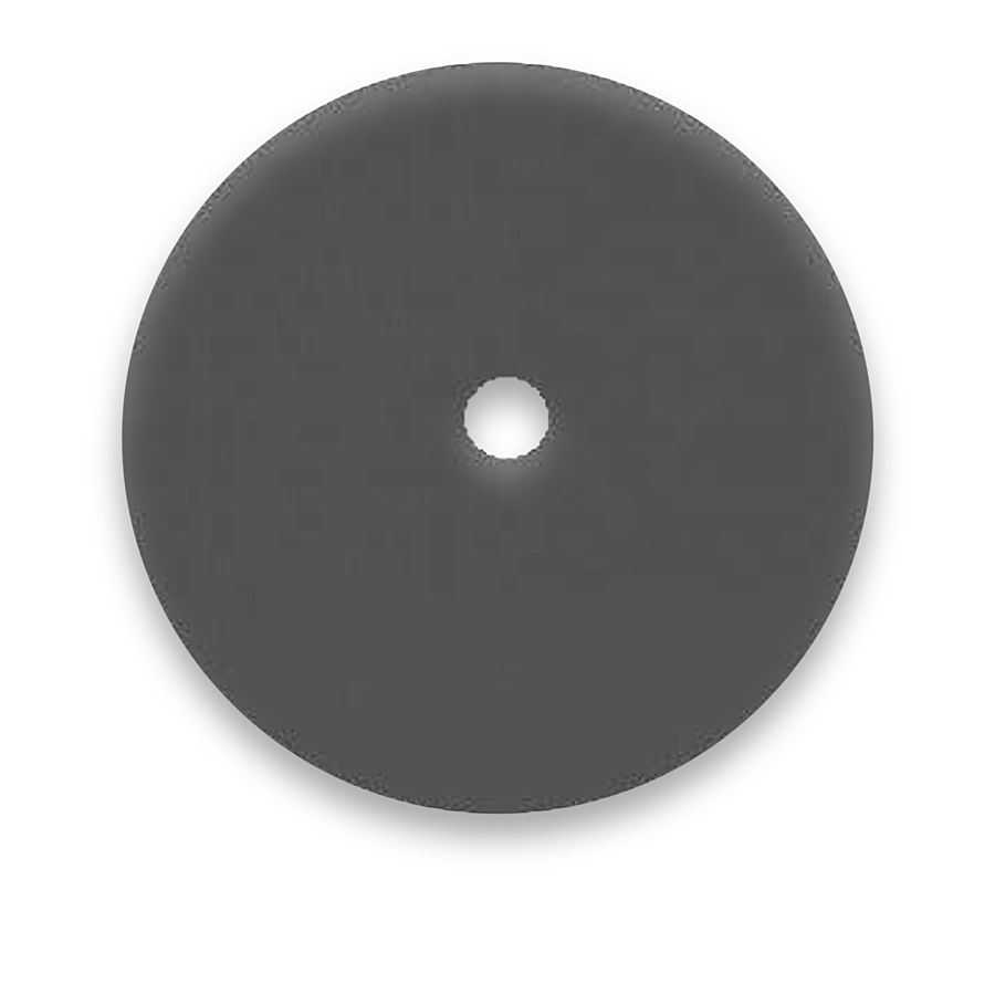
Optical Pinhole Patterns on Glass — CG10

CG10

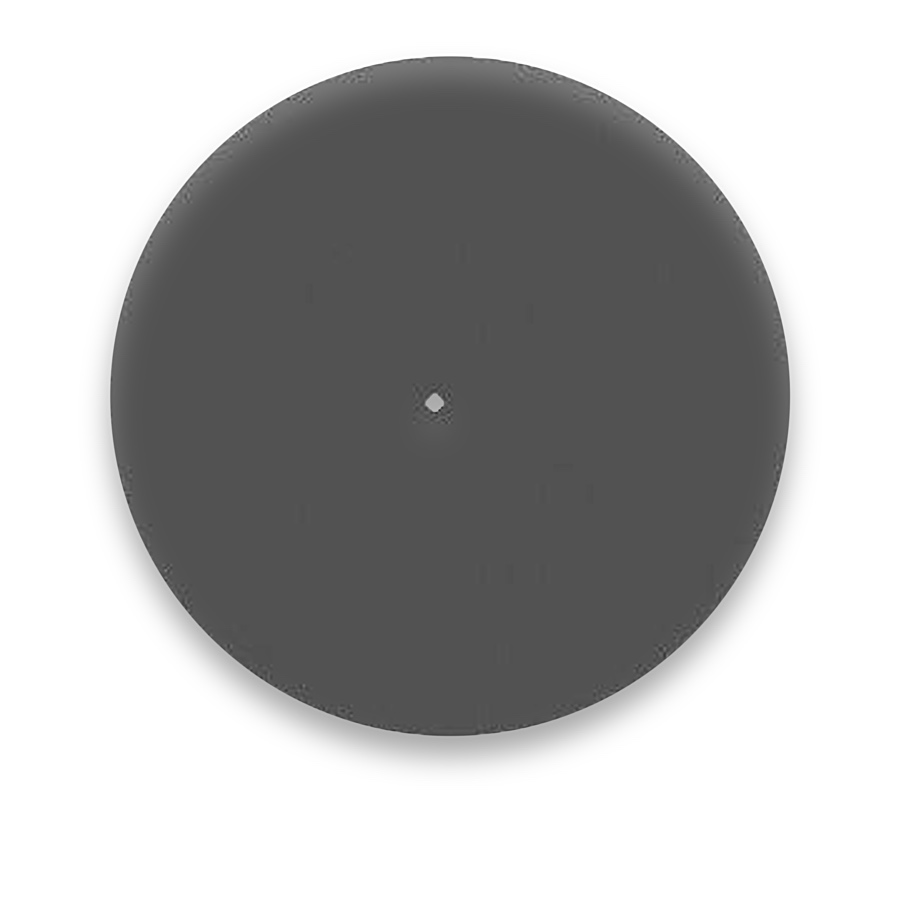
Optical Pinhole Patterns on Glass — CG25

CG25

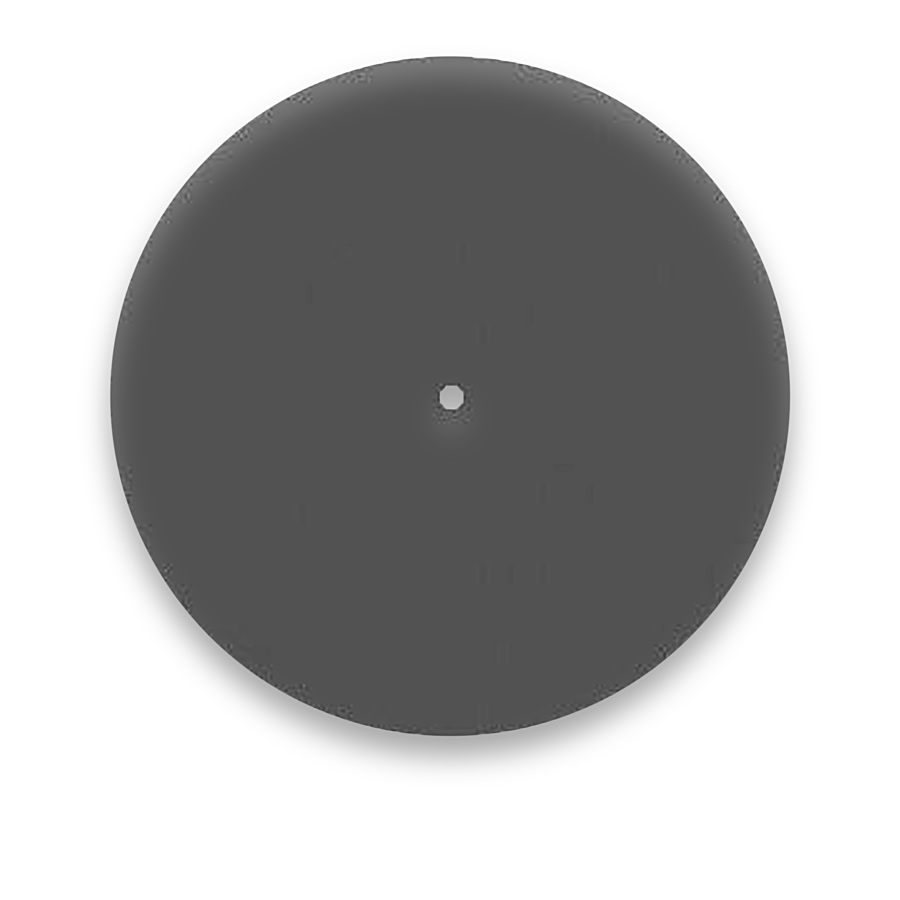
Optical Pinhole Patterns on Glass — CG50

CG50

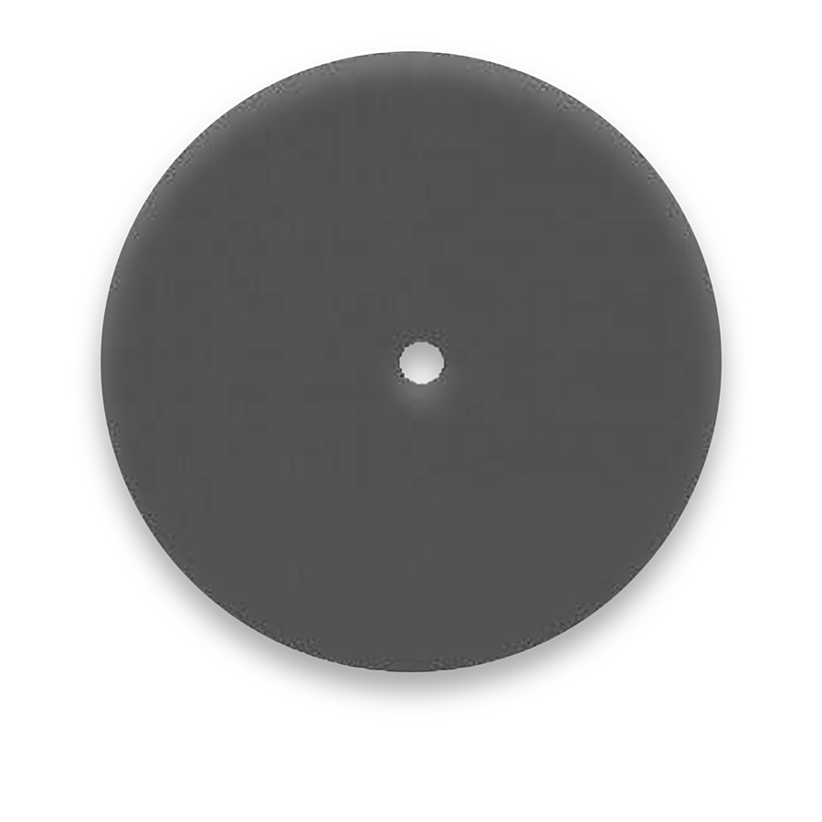
Optical Pinhole Patterns on Glass — CG100

CG100

Common questions

Is there a physical hole beneath a clear pinhole?

No. The opening is in the film; light continues through the glass substrate.

Can a pinhole array serve as a camera target?

Yes, if the illumination, coordinate geometry and feature detector are compatible. Bright apertures and dark dots may need different detection settings.

Is visible opacity enough for a laser application?

No. Wavelength, power density and exposure conditions affect suitability. Aperture geometry by itself establishes neither damage threshold nor laser-power handling.

Related pattern choices

Selection notes

Optical pinhole patterns form small transmitting points in an opaque film on glass for local optical paths and position references.

Define diameter and location at the film plane, then specify glass outline, thickness and the viewing face.

Information for your inquiry

Aperture diameter, coordinates, polarity, substrate, active field and mounting geometry.

Can a single pinhole be extended into an array?

Multiple openings can be defined in the same artwork, each with a diameter, coordinate and spacing to form the required array.

Search