Extend the optical path into the UV
JGS-1 is a useful starting material when conventional optical glass no longer covers the required short wavelength.

JGS-1 UV-grade fused silica slides, windows, plates and substrates for ultraviolet optical paths, spectroscopy, microscopy and precision instruments.
Use JGS-1 for custom slides, coverslips, windows, plates, discs and substrates when ultraviolet transmission matters. The finished component is defined by its working wavelength, thickness, clear aperture, surface condition and acceptance method rather than by the material name alone.
Specify the working wavelength and thickness together because both affect how transmission data should be interpreted for the finished part.
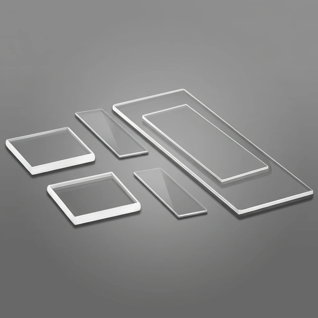
Use the material where the optical path, finished geometry and acceptance wavelength must be considered together.
JGS-1 is a useful starting material when conventional optical glass no longer covers the required short wavelength.
Low thermal expansion supports windows, plates and substrates whose geometry matters as temperature changes.
Define wavelength, thickness, surface condition and test method so the finished component can be checked against a meaningful requirement.
Begin with the working wavelength and component thickness. Then define geometry, clear aperture, flatness, parallelism, surface quality and any coating or patterned area required by the optical system.
| Property | Specification |
|---|---|
| PropertyMaterial | SpecificationSynthetic fused silica, JGS-1 UV grade |
| PropertyCommonly cited spectral range | SpecificationApproximately 185–2500 nm; confirm at the operating wavelength |
| PropertyAvailable forms | SpecificationSlides, coverslips, windows, plates, discs and optical substrates |
| PropertyDimensions and thickness | SpecificationDefined by the approved drawing |
| PropertyOptical surfaces | SpecificationFlatness, parallelism, roughness and surface quality defined by the drawing |
| PropertyCoating or patterning | SpecificationReviewed for the wavelength, geometry and process |
| PropertyTransmission acceptance | SpecificationSpecify wavelength, thickness, measured area and test conditions |
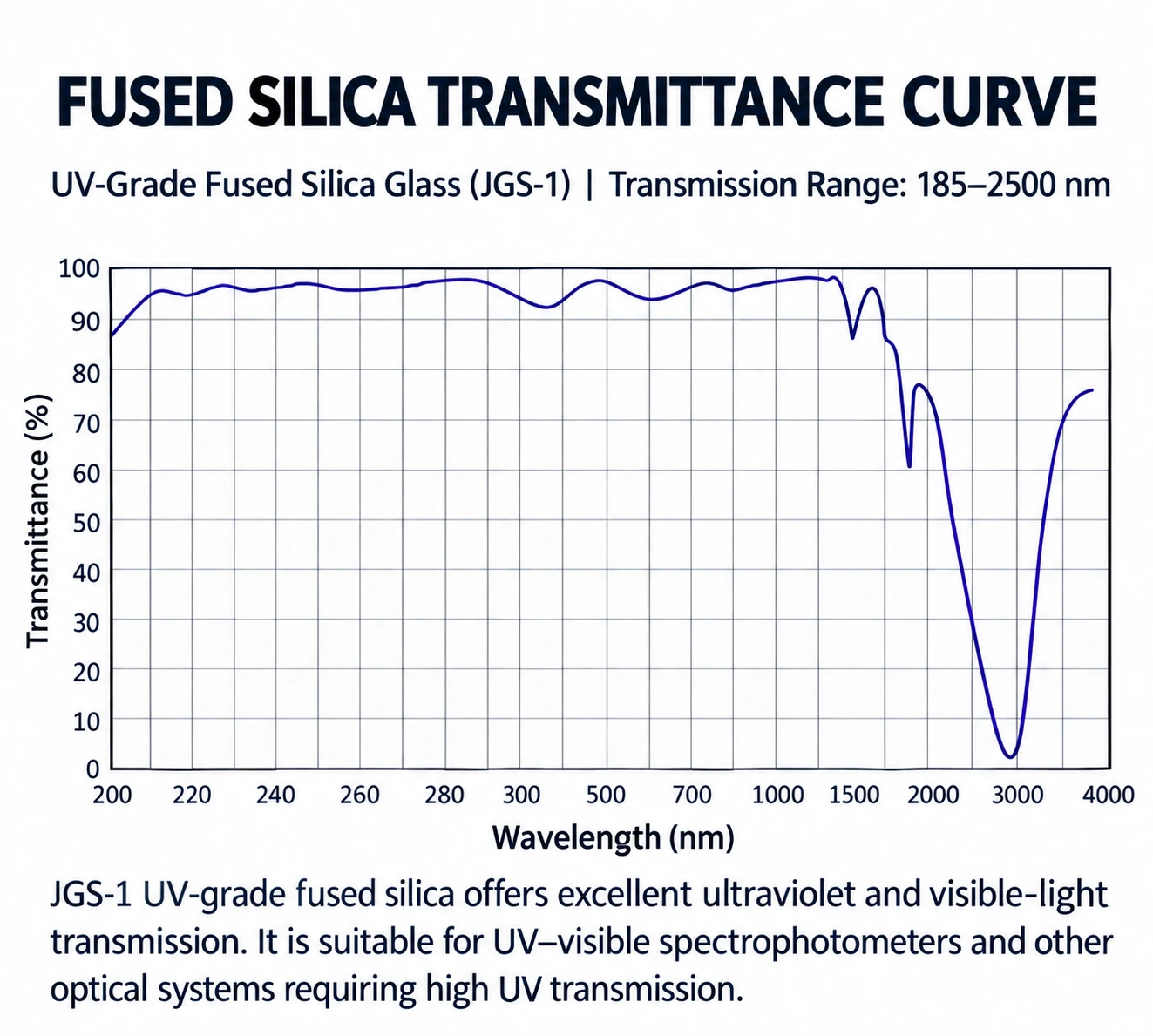
The supplied curve illustrates the expected UV-to-near-infrared behavior of JGS-1 and the OH-related absorption region near 2.7 µm. It is useful for material screening, but it does not include the sample thickness, surface state or measurement method required for product acceptance.
These commonly cited ranges are a screening guide. Supplier data, thickness and the material certificate remain the basis for a final decision.
| Material grade | Commonly cited range | Selection priority |
|---|---|---|
| JGS-1 | Approximately 185–2500 nm | Deep-UV transmission |
| JGS-2 | Approximately 220–2500 nm | General UV-visible optics |
| JGS-3 | Approximately 260–3500 nm | Longer-wave infrared priority |
Begin with the working wavelength and component thickness. Then define geometry, clear aperture, flatness, parallelism, surface quality and any coating or patterned area required by the optical system.
Material, dimensions, surface, pattern, coating and documentation can be reviewed together when the standard configuration is not enough.
JGS-1 material, outline, thickness, clear aperture and edge finish
Flatness, parallelism, surface quality, roughness and wavelength-specific transmission
Coating or patterned area, cleaning, packaging and inspection records
Short answers to the questions that affect material choice, pattern definition and acceptance.
It is commonly selected for UV optical paths, spectroscopy components, specialized microscope slides, windows and precision substrates. Final suitability depends on the working wavelength and finished-component specification.
It is a commonly cited material range, not a guarantee of equal transmittance at every wavelength. Confirm the required transmission at the operating wavelength, component thickness and agreed test conditions.
Yes. Dimensions, thickness, surface condition and edge treatment should be defined around the holder, imaging plane and handling method.
No material designation alone confirms laser suitability. Specify wavelength, pulsed or continuous operation, fluence or power density, coating, surface quality and the required damage threshold for engineering review.
JGS-1 is the usual starting point for deeper-UV transmission. JGS-2 is generally considered for UV-visible use, while JGS-3 is often considered when longer-wave infrared transmission is the priority. Use the actual supplier data and certificate for final selection.
Confirm these items after the product type and core parameters are selected. They define how the finished component is manufactured, checked and documented.
Inspect material identification, dimensions, thickness, clear aperture, optical surfaces and any agreed wavelength-specific transmission against the approved drawing. Transmission acceptance must state the sample thickness and measurement conditions.
Send the drawing, reference artwork or preliminary specification for manufacturing and inspection review.
Discuss this product