
Chrome Amplitude Gratings: Duty Cycle and Order Efficiency
A chrome-on-glass amplitude grating is defined by three numbers — period, clear width and duty — not by pitch alone. Each duty sets a fixed distribution of diffraction orders, and the drawing has to state which stripe the micrometres refer to.
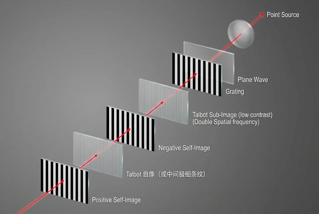
What the part does, in one paragraph
If your system needs a periodic optical reference — a fringe pattern, an alignment grating, a beam splitter, a spatial-frequency reference — the useful question is not "what pitch can you make" but "what duty do I need, and can the part hold it".
A chrome amplitude grating is a glass plate with a periodic chromium pattern. Where chrome remains, light is blocked; where the film is cleared, light passes. Because the pattern is binary, the transmitted field is a square wave, and a square wave has a fixed set of diffraction orders whose relative powers are decided by the duty cycle alone. That single fact is why this product is easy to specify badly: two drawings that both say "10 µm pitch" can describe parts whose zero-order transmission differs by a factor of five.
The pattern is written photolithographically and inspected as geometry: period, clear width, orientation, film continuity. What the finished component does to a beam also depends on the illumination, the substrate and the detector arrangement, so this page separates what a drawing can fix from what only the optical design can settle.
Period, clear width and duty: the three numbers
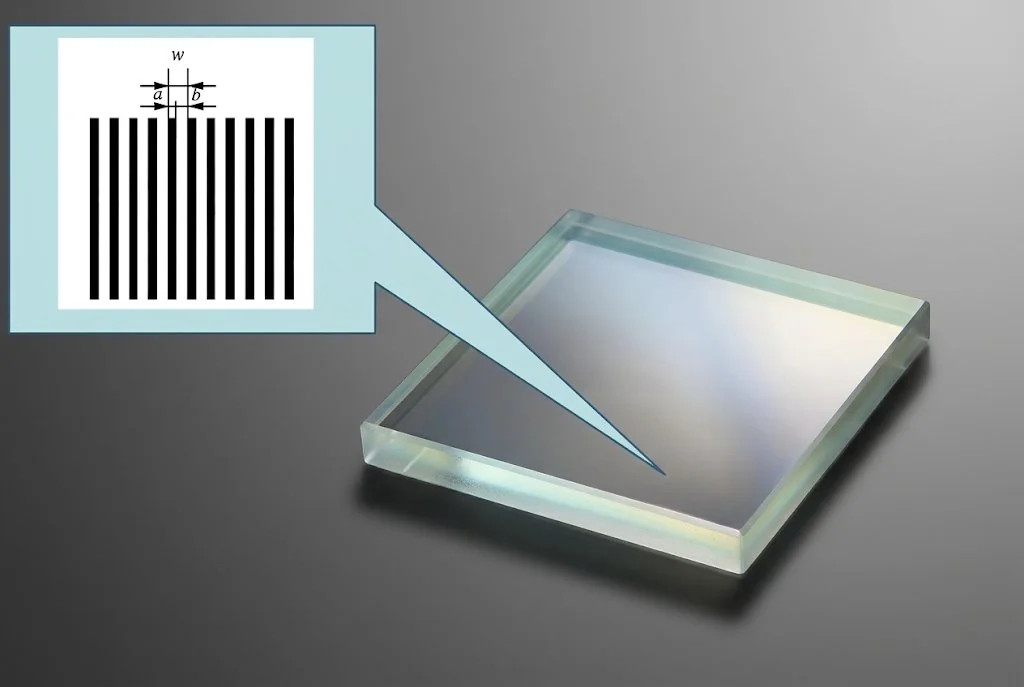
The pattern repeats. One repeat contains one opaque stripe and one clear stripe; the repeat distance is the period p. The transmitting stripe is the clear width c, and the ratio between them is the duty.
f = c / p chrome width = p − c
The reason this matters is that "line width" is not a number until you say which line. A note reading "3 µm lines at 10 µm pitch" fits a 30% duty and a 70% duty equally well, and the two are not interchangeable: they put the same power into the ±1 orders, but they differ enormously in what continues straight through (9% against 49% of the incident power). A throughput or efficiency check will not separate them either, because both look correct under a microscope.
Two conventions work in practice. Give the period and the clear width in micrometres, and let the chrome width be the remainder; or give the period and the duty as a decimal or a percentage. Do not give a duty alone — once the period is rounded to a convenient number, the duty no longer determines a unique clear width.
Where the light goes
For a binary amplitude grating with an ideal square profile, the fraction of incident power in order m is fixed by the duty.
I(m) / I(in) = sin²(π m f) / (π m)² (m ≥ 1)
I(0) / I(in) = f²
Two consequences follow directly. First, the ±1 orders are strongest at 50% duty, where each carries 10.1% of the incident power — and 50% duty is also where the second and every other even order vanishes. Second, a duty of 1/n removes the n-th order completely: 1/3 removes the third, 1/4 removes the fourth. This is the mechanism behind "phase-shift-like" duty choices in fringe work, and it costs nothing to specify.
| Duty | Clear width | Zero order | ±1, each | ±2, each | ±3, each |
|---|---|---|---|---|---|
| 0.25 | 2.5 µm | 6.3% | 5.1% | 2.5% | 0.6% |
| 0.33 | 3.3 µm | 11.1% | 7.6% | 1.9% | 0% |
| 0.50 | 5.0 µm | 25.0% | 10.1% | 0% | 1.1% |
| 0.70 | 7.0 µm | 49.0% | 6.6% | 2.3% | 0.1% |
| 0.80 | 8.0 µm | 64.0% | 3.5% | 2.3% | 1.0% |
A detail that decides whether you should be buying this part at all: the orders must add up to the clear fraction. At 50% duty, half the light is blocked by the film, and the ±1 pair carries 20.3% of the incident power — about 40% of what gets through the plate. Everything else is in the zero order and higher orders. If the system needs most of the light in one order, a phase or blazed element is the right component, not a chrome grating; no supplier can raise the 10.1% figure by making a better chrome grating.
Angle: where the orders land
The period also sets the angle. For normal incidence the grating equation gives the direction of each order, and the first order is the one most designs use.
sin θ(m) = m λ / p
The practical version: on a 100 mm focal plane, a 10 µm period at 633 nm puts the ±1 orders about 6.3 mm either side of the axis, and the ±2 orders about 12.8 mm out. Those numbers decide the detector size, the lens aperture and whether the second order is even collected — and they are arithmetic, not a property of the plate.
There is a hard cutoff as well. An order propagates only while λ/p < 1, so a period shorter than the wavelength produces no diffracted order at all: at 405 nm only the direct beam survives once the period drops below 405 nm, and between 405 nm and 810 nm the first order is the only one that exists. A specification that asks for a period close to the wavelength is really a specification for a different optical component.
Which route can hold your period
The smallest feature on the plate is not the period; it is whichever of the clear and chrome stripes is smaller. At 50% duty they are equal and the period is twice the minimum feature. Away from 50% duty the relationship tightens quickly: at 30% duty the clear stripe is 0.30 × the period, so a 2 µm period asks for a 0.6 µm clear stripe, which is already finer than the 1 µm process figure.
| Route | Min feature | Min period at 50% duty | Width tolerance | Optical density | Where it fits |
|---|---|---|---|---|---|
| Chrome on glass, fused silica or soda-lime | 1 µm, or 0.55 µm option | 2.0 µm, or 1.1 µm option | ±0.2 µm | OD 3 yellow, OD 5 blue | Transmitted gratings on a stable substrate; the fine-period route |
| Chrome on ceramic, zirconia or alumina | 2 µm polished, 4 µm matte | 4.0 µm, or 8.0 µm matte | ±0.2 µm line width, ±2 µm feature position | Finish-dependent reflectance | Reflective geometry only; the substrate does not transmit |
| Photographic film, silver halide | 10 µm, or 30 µm | 20 µm, or 60 µm | ±10 µm | OD > 4; grayscale tone option | Large or lightweight patterns; coarse fringes |
Industry reference only. These figures describe published options; they do not represent a guaranteed specification for an arbitrary drawing. Final requirements must be reviewed and agreed in writing, against the substrate, the pattern and the inspection plan for the specific order.
Choosing between this part and its neighbours
| Option | What it does | Order budget | When it is the right part |
|---|---|---|---|
| Chrome amplitude grating | Blocks or transmits; binary square profile | Up to 10.1% per ±1 order at 50% duty | Spatial reference, fringe pattern, alignment, beam sampling where efficiency is secondary |
| Phase grating | Modulates phase through relief or index | Set by etch depth and wavelength | Higher efficiency in one or two orders with no absorption |
| Blazed grating | Sawtooth relief steers light into one order | Most of the power into the design order | Spectroscopy and monochromators, where one order must dominate |
| Ronchi ruling | Periodic bars used as a test target | Same binary physics, different specification | Focus, resolution and MTF work where the pattern is judged, not measured in orders |
The drawing and the RFQ
The drawing decides whether the part can be made once, correctly. These are the fields that a grating drawing needs beyond a title block.
- 1 · Period and clear widthBoth in micrometres, with the duty added as a cross-check. This is the pair of numbers the inspector measures, and the pair that decides the optical behaviour. (Number)
- 2 · Stripe direction and datumWhich way the stripes run, and which plate edge or fiducial the pattern is located from. A rotated grating diffracts in a different plane and looks identical under a microscope. (Number)
- 3 · Active area and edge exclusionThe region that must carry a continuous pattern, and the border where a handling mark, a chip or a particle is acceptable. Without it, the first scratch decides the acceptance. (Number)
- 4 · Pattern polarity and film sideOpaque stripes on a clear field or the reverse; and which face carries the film. The film side changes the optical path length and the reflection you will see. (Fit)
- 5 · Working wavelength and illuminationThe wavelength sets the order angle; the illumination decides how much of the pattern is coherent enough to diffract. A converging or divergent beam is not the same measurement as a collimated one. (Number)
- 6 · Glass grade, thickness and flatnessFused silica or soda-lime, the thickness from the published options, and the flatness stated over a measured length rather than as a single word. (Fit)
- 7 · Optical density or finishWhich chrome, and whether the application needs the lower reflectance or the higher density. State the wavelength at which the value is meant. (Fit)
- 8 · Outline, chamfer and handling zoneOverall size, corner radii, cut quality and any feature that must survive handling after patterning. (Fit)
- 9 · Inspection method and recordWhat is measured, over what area, with what instrument, and what document you need at delivery. If a diffraction measurement is required, its geometry belongs here too. (Traceability)
- 10 · Quantity, packaging and revisionPrototype or series, how the parts are separated and protected, and the drawing revision that the artwork and the inspection record both reference. (Traceability)
Three things do not need to be on the drawing because they belong to the conversation: the application, the system-level performance you expect, and any standard your customer requires you to test against. Send them with the enquiry. They often change the recommendation before anything is cut.
Inspection and acceptance
A grating is accepted on geometry and film condition. That is checkable on a bench, before the part is installed, and it is what the drawing can control.
- Period over many periods. Measuring one period tells you almost nothing; the useful number is the cumulative distance over 20 or 50 periods, divided back. The same measurement catches a systematic pitch error that a single-period check hides.
- Clear width at several positions. Centre and both ends of the active area, because a dose or development gradient shows up as a duty drift rather than as a period error.
- Edge quality against the stripe width. Published edge roughness is 30 nm 3σ in the first writing configuration. On a 0.75 µm clear stripe that is 4% of the width; on a 5 µm stripe it is 0.6%.
- Film continuity. Pinholes in a chrome stripe and chrome bridges in a clear stripe are both pattern defects, and both matter more as the duty moves away from 50%.
- Optical density. Measured on the film at the agreed wavelength. OD 3 transmits about 0.1% and OD 5 about 0.001%, which caps the pattern contrast at roughly 950:1 or 95 000:1 against a clear area above 95%.
- Orientation and identification. Stripe direction relative to the datum, plus the revision mark that ties the part to its artwork.
Duty error is worth one calculation, because it explains why two nominally identical drawings behave differently. On a 10 µm period, the ±0.2 µm line-width tolerance is a 2% duty uncertainty. At 50% duty the ±1 order changes by about 0.4%; at 30% duty the same error changes it by about 9%. The flat part of the curve is the safe part of the design, and it is also the strongest.
Common questions
Is a chrome amplitude grating the same as a blazed grating?
No. A chrome grating is binary: each point of the period either transmits or blocks. A blazed grating uses a sawtooth relief to steer most of the light into one order. With a 50% duty chrome grating, the ±1 orders carry about 10.1% of the incident power each, which is a ceiling set by the geometry rather than by the supplier.
Should the drawing give the duty cycle or the clear width?
Give the period and the clear width in micrometres, and add the duty as a cross-check. Duty alone is ambiguous once the period is rounded, and "line width" alone does not say which stripe is meant. The chrome width is then the period minus the clear width, and the inspector has one number to measure on each feature.
Why is my measured first-order power lower than the calculated value?
The 10.1% figure assumes an ideal square profile, no absorption in the clear areas and no reflection. A real part adds Fresnel reflection at both glass faces, absorption in the substrate, edge roughness on every stripe, and a finite illuminated area that broadens each order. If the measurement uses a converging beam or a wide angular aperture, part of the order falls outside the detector.
What is the finest period that can be quoted?
The limit follows from the minimum feature and from the duty, not from the period alone: at 50% duty the period is twice the minimum feature, and away from 50% it is the minimum feature divided by the smaller of f and 1 − f. TL OPTIK publishes a 1 µm process figure and a 0.55 µm option for chrome on glass, so the shortest period to discuss at 50% duty is about 1.1 µm to 2.0 µm. Every case still needs the drawing and the process route confirmed.
Can the grating be supplied with a sinusoidal profile?
Not in chrome. A chrome-on-glass pattern is binary because the film is either present or removed. The published material options list a photographic film route with a sinusoidal grayscale tone, but that route has a 10 µm or 30 µm minimum feature and a ±10 µm feature accuracy, so it suits coarse fringe projection rather than fine order control.
Does a higher optical density improve the grating contrast?
It raises the ceiling on it. OD 3 transmits about 0.1% through the dark stripe and OD 5 about 0.001%, against roughly 95% through the clear stripe, so the pattern contrast is limited to about 950:1 or 95 000:1 by the film. Whether the system reaches that value depends on stray light, reflections and the detector, which are outside the part.
Send the period and the duty, not just the pitch
A grating can be quoted precisely once the pattern is defined. Tell us the period, the clear width or duty, the active area and the working wavelength, and the substrate, film and inspection record can be matched to it — or challenged before anything is written.