
Optical Slit Plates
Separate slit geometry, coating polarity and substrate so a slit plate can be manufactured, illuminated and inspected against one drawing.
Define the slit as geometry, polarity and substrate
A workable slit specification states three things separately: the opening geometry (width a and length L with their tolerances), the polarity that decides whether the slit appears bright on a dark field or dark on a bright field, and the substrate that carries the pattern and stays part of the optical path.
| Route | What the viewer sees | Typical use | State on the drawing |
|---|---|---|---|
| Clear slit in an opaque coating | A bright line on a dark field, in transmitted light | Defining a line-shaped source or field stop | Coating material and optical density, slit width and length, edge quality |
| Opaque line on a clear or frosted substrate | A dark line on a bright field | Alignment, comparison and demonstration setups | Line width and length, substrate surface condition, observing side |
Do not order a slit from a photograph or a width name alone. The same nominal geometry behaves differently depending on polarity, illumination and substrate, and an unstated tolerance turns the most important dimension of the part into an assumption.
Slit plates and where they are used
A slit plate is a planar glass component with one or more line-shaped openings or lines produced by photolithography. Single slits define a line-shaped source or field stop; double slits and slit arrays add controlled spacing for interference work; opaque lines on clear substrates serve alignment and comparison setups.
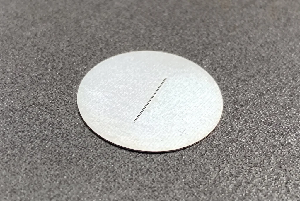
The photograph shows a coated circular plate with one slit opening. It demonstrates a form factor, not a catalogue of fixed sizes. Final substrate, geometry and coating follow the approved drawing.
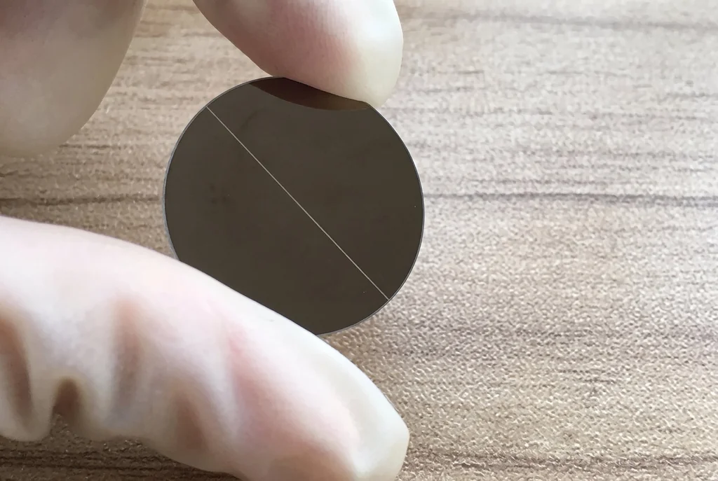
Slit plates belong to the transmitted-light part of an instrument. They are not mirrors, filters or windows: their function comes from a defined opening, not from a surface treatment over a full aperture. If the requirement is a round opening instead of a line, an aperture plate is the closer product family.
How slit geometry and polarity work together
Slit width a controls how much light passes and how narrowly the transmitted field is defined. Slit length L covers the extent perpendicular to the width, so it decides how much of the scene or beam line remains inside the opening. Polarity decides what the observer or detector compares the slit against: a clear opening in an opaque coating appears bright in transmitted light, while an opaque line on a clear or frosted substrate appears dark against a bright field.
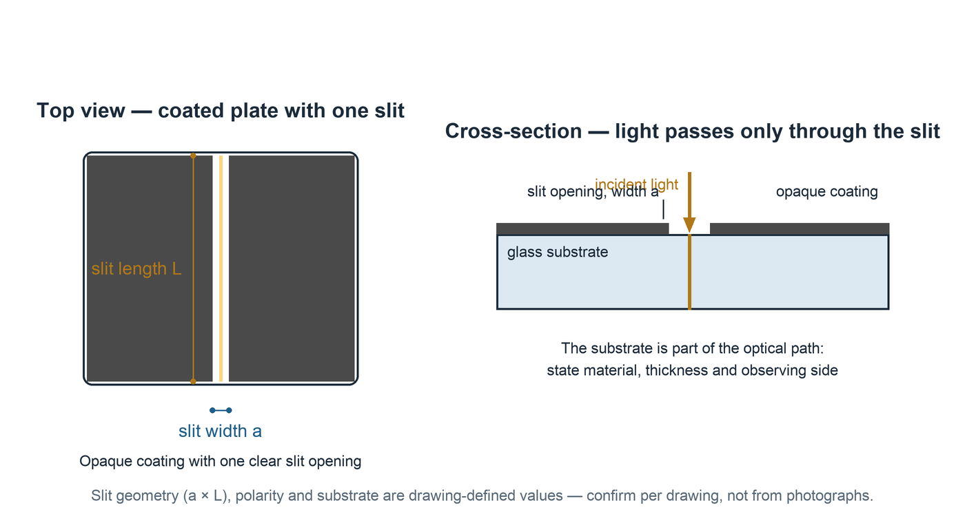
The substrate completes the optical behaviour. A polished substrate keeps the slit image sharp for direct projection; a frosted or opal substrate diffuses the transmitted light, which is useful when the slit must be visible from many viewing angles. These are different optical results, so the surface condition belongs on the drawing next to the geometry.
Choosing the slit specification
Work from the optical layout backwards to the drawing. The conditions below decide the specification together; none of them can be inferred reliably from a product photograph.
| Condition | Why it matters | What to state |
|---|---|---|
| Illumination and wavelength | Coating opacity and substrate transmission change with wavelength | Light source, wavelength band and incidence side |
| Slit width a and length L | Width controls throughput and the transmitted field; length covers the extent perpendicular to it | Nominal value, tolerance and measurement method for each opening |
| Polarity | Decides whether the slit appears bright-on-dark or dark-on-bright | Clear opening in coating, or opaque line on substrate |
| Substrate | Polished and frosted surfaces transmit the slit image differently | Material, thickness, surface condition and observing side |
| Mounting and orientation | The slit only works as intended at the planned orientation | Orientation reference, handling area and mounting state |
Put every decision on one drawing
- Application and illuminationState what the slit defines in the instrument, the light source, wavelength band and the side the pattern is observed from.
- Slit geometryDimension width a and length L for every opening, with tolerances, the number of slits and their spacing when more than one.
- Polarity and coatingChoose a clear opening in an opaque coating or an opaque line on a clear field, and name the coating material and opacity condition.
- SubstrateName the material, finished thickness and surface condition, and keep handling or mounting areas outside the slit region.
- Outline and datumsDimension the outline, thickness and the datums that fix slit position and orientation in the housing.
- Quality and recordsState edge-quality limits, appearance requirements, quantity and the measurement records required with delivery.
Make inspection conditions reproducible
A slit width result can only be compared with a limit when the measurement method, positions and drawing revision are known. The measured geometry of the plate and the performance of the complete optical system are separate records: the plate proves the opening, the system proves the result.
| Item | Acceptance condition | Record |
|---|---|---|
| Slit width and length | Drawing values with named measurement method and positions | Measured values, instrument and drawing revision |
| Edge quality | Agreed limits for burrs, flare and edge straightness | Inspection method and observed result |
| Coating and polarity | Named face, optical density or opacity condition and wavelength | Measurement conditions and result |
| Substrate | Material, thickness, surface condition per drawing | Measured dimensions and surface condition |
| Orientation and appearance | Orientation reference, pattern placement and appearance limits | Observed result and inspection area |
Questions before ordering
Is a narrower slit always the better choice?
No. Slit width trades transmitted light against the width of the transmitted field and diffraction spreading. A width that is too narrow for the illumination and detector can leave the system light-starved, while a width that is too wide blurs the definition the slit was meant to provide. Choose the width from the optical layout, not from habit.
Is a slit the same as a scored or printed line on glass?
No. A slit is a defined opening between two clean edges in an opaque film, or an opaque line on a clear substrate produced through a photolithographic process. Edge straightness, edge quality and the absence of burrs or flare are part of the specification; a scored or printed line does not automatically provide them.
When is a double slit or slit array used instead of a single slit?
A single slit defines one line-shaped opening. Double slits and slit arrays add controlled spacing between openings, which is the basis of interference and multi-channel experiments. If more than one opening is required, the spacing, the relative width and the orientation of every opening must be defined on the drawing as well.
Why does the substrate matter for a slit plate?
The substrate is part of the optical path. A polished substrate transmits the slit image directly; a frosted or opal substrate diffuses the light and changes how the slit appears from the viewing side. Material, thickness and surface condition therefore belong on the drawing together with the slit geometry.
What information is needed for a first quotation?
Send the outline and thickness, substrate material, the slit width and length with their tolerances, the number and orientation of slits, the polarity (clear slit in an opaque field or opaque line on a clear field), the coating or surface requirement, and the quantity. A sketch is enough to begin feasibility review.
Send your slit specification
A sketch with the outline, slit geometry, polarity, substrate and quantity is enough to begin review. Final tolerances and inspection records can then be aligned with the actual instrument.