
Choosing a Counting Reticle: Estimator, Edge Rule and Sample Size
A counting reticle is a sampling instrument, not a picture of a grid. The quantity you must report decides the pattern, the pattern's edge decides the count, and the number of fields decides whether the number you write down can be defended.
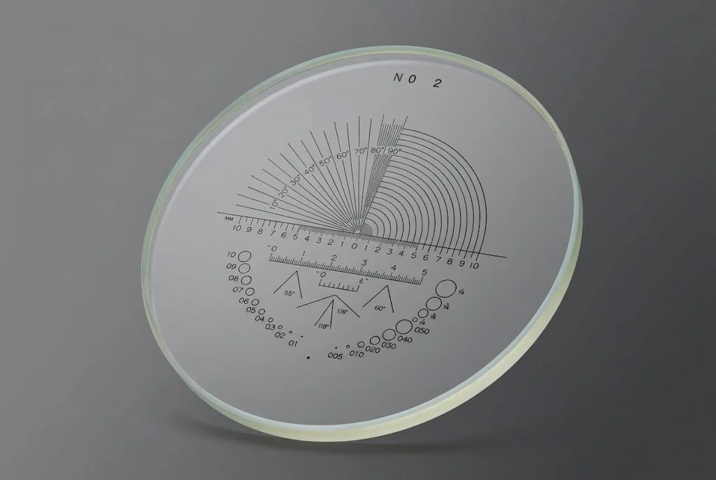
Decide the quantity before the pattern
Objects per area needs a grid with a calibrated cell area and a written edge rule; fraction of area needs a point array and enough points for the precision you claim; boundary crossings need a defined test-line length; size distribution needs a comparison series and a stated size convention. The pattern follows the estimator, and the estimator decides what the drawing has to carry.
Most reticle enquiries arrive as a picture: "we need this grid", with a screenshot attached. The picture is usually the right shape and the wrong instrument, because the number the laboratory ultimately reports has not been separated from the tool used to observe it.
Two laboratories can hold identical grids and publish numbers that differ by twenty per cent, without either of them making an arithmetic mistake. One counted everything touching the frame; the other counted objects cut by two edges only. One read eight fields; the other read thirty-six. Both wrote "counts per field". Neither wrote down what a field was.
A count is not a quantity
Four different results hide behind the word count, and each one is estimated by a different operation on the image. This is the first thing to settle, because the pattern cannot be chosen until it is.
| Quantity reported | What the operator counts | What the pattern must carry |
|---|---|---|
| Objects per unit area | Objects satisfying the edge rule, divided by the calibrated field area | A grid or frame with known pitch, and edges visible enough to apply the rule |
| Fraction of area occupied by a phase | Points landing on the phase, divided by eligible points | A defined number of points, evenly spaced, with no preferential placement |
| Boundary crossings per unit length | Boundary intersections, divided by the total test-line length | Test lines of stated length, with visible endpoints and a defined orientation |
| Size distribution | Particles per size class, divided by particles counted | A comparison series with defined diameters and a stated size convention |
| Particles per unit volume | Objects, divided by counted area multiplied by chamber depth | The counted area only — depth comes from the chamber, not the reticle |
| Fibres per field, or share of fields positive | Qualifying fibres, or fields containing them, over fields examined | A circular field boundary and reference marks, matched to the method version |
The fifth row is where most of the confusion lives. A grid defines an area, and an area alone is not a concentration. The volume term comes from the chamber and its cover, which is why counting grid reticles and counting chambers are separate purchases with separate acceptance criteria. The guide to reticles in microscopes and measuring instruments works through the concentration arithmetic; this page stays with the sampling decisions.
The distinction matters commercially as much as technically. A square grid can be read as a set of intersections and used for point counting — but only after the number of eligible points and the eligibility rule are written down, which is a different pattern decision. What no family can do is substitute for another: a comparison series cannot produce an area fraction, and a grid of unknown pitch cannot produce a density. The pattern either contains the sampling frame the estimator needs or it does not, and the operator cannot add it afterwards.
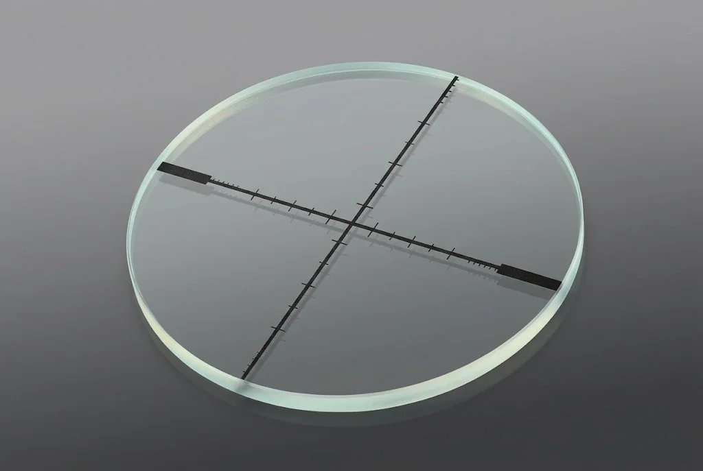
The edge rule decides the number
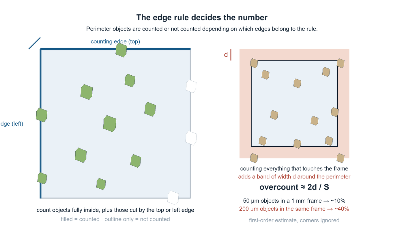
Every counting frame has an edge, and every edge cuts objects in half. The rule for those cut objects is the single largest source of disagreement between operators who are otherwise following the same procedure — and it is almost never written down.
| Convention | What the operator does | What it assumes | Where it breaks down |
|---|---|---|---|
| Centre in frame | Counts the object only if its centre lies inside the frame | The centre of an irregular outline can be located consistently | Faint, clustered or elongated particles: two operators place the centre differently |
| Half weight | Counts every straddling object as one half | The object is small compared with the frame, so the edge cuts it near its middle | Large objects on a small frame: the fraction inside is not one half, and the weights drift |
| Two adjacent edges | Counts objects fully inside, plus those cut by the top or left edge only | The frame is a sampling window, and each object belongs to exactly one window | The two edges must be visible and marked, or the operator has to remember which they were |
The penalty for skipping the rule is easy to estimate. Objects whose centres lie within half an object diameter of the frame contribute an additional band of area around the perimeter. For a square frame of side S and objects of diameter d, that band is about 2·S·d, so the relative overcount is roughly 2d / S. At 50 µm objects in a 1 mm frame, the overcount is about ten per cent. At 200 µm objects in the same frame it is about forty per cent — the difference between two suppliers' data sheets on the same material, with no instrument error anywhere in the story.
The two-adjacent-edges rule is unbiased when the frame is treated as one cell of a tiling, or when field positions are chosen without reference to where the objects happen to be. A single field picked because it looked representative does not become unbiased because two edges were excluded; the rule controls the perimeter, not the choice of field.
How many fields the number actually needs
Precision in counting comes from the number of things counted, not from the elegance of the pattern. For objects distributed at random, the relative standard error of a count falls as the square root of the count: RSE = 1 / √N. A point fraction behaves similarly, with the additional penalty that a rare phase is harder to measure than a common one, because most of the points miss: RSE = √((1−p) / (N·p)).
| Phase fraction p | RSE 20% | RSE 10% | RSE 5% |
|---|---|---|---|
| 0.05 | 475 | 1,900 | 7,600 |
| 0.10 | 225 | 900 | 3,600 |
| 0.25 | 75 | 300 | 1,200 |
| 0.50 | 25 | 100 | 400 |
Read the highlighted row as a purchasing decision. A laboratory that must report a ten per cent phase fraction to ten per cent relative precision needs 900 points. With the 25-point array listed for the point-counting family, that is 36 fields. A 24-point array gives 38 fields. The difference between a 24-point and a 25-point array is irrelevant to the result; the difference between either of them and eight fields is not.
Two numbers are worth remembering. Counting 100 objects gives a relative standard error of about ten per cent. Counting 2,500 gives about two per cent. If a report states a count density to two significant figures without saying how many objects were counted, the statement usually cannot be checked — and often cannot be reproduced.
What the curves leave out
These relations assume that the objects are distributed randomly and that field-to-field variation is negligible. In a rolled sheet with banding, a settled suspension with a gradient, or a coating with a thickness trend, the field-to-field term dominates. In that case adding fields helps far more than adding points to each field, because a new field samples a new part of the specimen while a new point inside the same field samples the same neighbourhood. The practical instruction is to count a handful of fields first, look at the spread between them, and only then decide how many more to read.
When the pattern and the specimen share a period
A regular array is a sampling device with its own frequency, and a periodic specimen has one too. If the two coincide, every point can land in the same phase, and the fraction you measure is the fraction of the array, not of the material. This is not exotic: laminated structures, drawn wire, coated strip, printed tracks and semiconductor arrays all produce it. The symptom is a result that looks impossibly clean — a fraction of exactly 0.00, 0.50 or 1.00, or a value that moves sharply when the stage is nudged.
Three habits remove most of the risk: observe the same field at two array orientations or two stage positions and compare — a result that survives a rotation is a property of the specimen; prefer a field selection that is not locked to the specimen geometry — random or systematic-random field starts are designed for this; and report the array count and the field selection rule alongside the result, because a fraction that cannot be reproduced from the written procedure is not yet a measurement.
Matching the pattern family to the estimator
The catalogue groups counting patterns by what they do to the image. The codes below are the designations used in the TL OPTIK reticle listings; they identify a layout, not a standard, and a layout is only useful when the estimator it serves is the one you need.
| Family | Codes listed | Estimator it serves | State when ordering |
|---|---|---|---|
| Counting grid | NG14 | Objects per area; field subdivision for systematic counting | Pitch, cell count, which edges are the counting edges, origin position |
| Point array | G54 · G55 · G47 · G50 · NG52 | Point fraction; area fraction under sampling assumptions | Number of points, spacing, whether all points are eligible |
| Test lines | NGW2 · GW3 · NGM1 · G49 | Intercept counting; boundary density along a known length | Total test-line length, endpoints, repeat spacing, orientation |
| Fibre field | G22 · G24 · G25 | Field-based fibre counting | Circle diameter, reference marks, pattern version |
| Comparison series | NG1 · NG2 · NG10 · G23 · NG30 | Size classes by visual comparison | Reference diameters, area progression, polarity of dark and clear features |
| Grain reference | G41 · G42 · G45 · G46 · NG21 | Comparison or intercept grain sizing | Field scale against the reference magnification of the chosen method |
| Inclusion reference | G44 · NG60 · NG61 | Class comparison for non-metallic inclusions | Comparison feature sizes, scale divisions, reference frame |
| Pharmaceutical field | G57 | Counting field with size references for particulate matter | Field geometry, size marks, the thresholds the method will apply |
Note what the table does not say. Two patterns with similar-looking circles are not interchangeable, and neither of them turns a procedure into a conforming test method. The layout code tells you what geometry was supplied; the method edition, magnification and counting rules establish the result.
What to put on the drawing
Seven items carry the pattern from a conversation into a component. Three of them change the number the laboratory will report; the rest decide whether the part fits and whether the record can be traced.
- 1 · Field diameter and outlineThe seat diameter, the supported edge and the overall outline. State the seat, not the housing: an eyepiece with the right outside diameter can still have an incompatible internal seat. (Fit)
- 2 · Thickness and pattern positionSubstrate thickness, and where the pattern plane sits relative to the faces. Both belong to the fit and to the focal position, and both are agreed as tolerances rather than described as "standard". (Fit)
- 3 · Pattern sideWhich face carries the film, and therefore whether the observer looks through the glass or at the coated surface. It changes the focal offset and the parallax behaviour of the finished assembly. (Fit)
- 4 · Active field boundaryThe edge of the region that is actually sampled. Everything outside it is handling zone, and an operator who includes it in the field area will report a density that is low by exactly the ratio of the two areas. (Number)
- 5 · Array count and pitchHow many points, marks or cells, at what spacing. This is the field that converts a pattern into an estimator, and it is the one most often left to the supplier's default. (Number)
- 6 · Label and orientation markA revision identifier and a mark that fixes rotation. Without them, a reprint cannot be compared with the part it replaces, and a rotated pattern produces a different result without looking different. (Traceability)
- 7 · Edge exclusion and handling zoneThe zone where a scratch, a chip or a particle does not affect the measurement. Defining it protects the supplier from rejecting a usable part and the customer from accepting a damaged one. (Fit)
What the reticle record can and cannot prove
A patterned component can be inspected as an optical part: pitch, cell count, point coordinates, orthogonality, line width, boundary marking, label legibility, centring relative to the outline, and the condition of the active field. Those are the items the reticle listings name for each family, and they are checkable before the part leaves the bench.
None of them is the measurement. A record that reports a correct 25-point array says nothing about the magnification it will be used at, the field area it will define in that instrument, the edge rule the operator will apply, or the number of fields the laboratory will read. The reticle manufacture and acceptance guide draws that line in more detail: component acceptance is one activity, installed verification is another, and method compliance is a third.
This is why the RFQ is worth doing properly. A supplier who receives a field diameter and a code will deliver a correct part for an unspecified measurement. A supplier who receives the estimator, the counting rule and the instrument magnification can question the pattern before the tooling is cut — which is the only point at which a change is still inexpensive.
Common questions
Can a counting grid give me a cell concentration in cells per millilitre?
No. The grid divides an area; concentration also needs a known depth and the dilution applied to the sample. Volume is the counted area multiplied by the chamber depth, and the depth belongs to the chamber and its cover, not to the reticle. The grid supplies the area term only.
Is a 25-point array precise enough for a reported phase fraction?
It depends on the fraction and on the precision you claim. At a 50% phase, 25 points give a relative standard error of about 20%. At a 5% phase the same 25 points give about 87%. A 25-point array is a screening tool; a reported fraction usually needs several hundred to a few thousand points, which means several fields.
Which two edges of the frame should be counted?
Top and left is the usual convention, but the choice is not physical: any two adjacent edges give the same result as long as the same two are used throughout the study. What matters is that the method names them and that the frame is visible enough for the operator to apply the rule without judgement.
Does a higher magnification improve the precision of a count?
Not by itself. Magnification shrinks the objects relative to the frame, which reduces the boundary band, but it also reduces the number of objects inside each field, so more fields are needed for the same total. Precision follows the number of objects counted, not the magnification used to count them.
Does a pattern with an ASTM or pharmacopoeial designation prove compliance with that method?
No. A pattern supplies geometry. The method edition, magnification, specimen preparation, blank and control handling, and the counting rules establish the result. A designation on a reticle tells you which layout was supplied, not that the laboratory's procedure conforms to the standard.
What should be included in an RFQ for a counting reticle?
Field diameter and mounting outline, the active field, the array count and pitch or the test-line length, label and orientation marks, pattern side, substrate and thickness, the instrument and magnification, and the counting rule the pattern is expected to serve. Quantity and the inspection record you need complete the request.
Send the counting rule with the pattern
A counting reticle can be quoted and made accurately once the estimator is known. Tell us what the laboratory must report and which rule it will apply, and the pattern, labels and inspection record can be matched to that task. Useful to include: the quantity to be reported and its unit; pattern family or code, array count and pitch; field diameter, active field and edge rule; substrate, thickness and pattern side; instrument, magnification and label requirements; inspection record and quantity.