Point-Counting Reticles

A defined array of test points provides a sampling frame for counting intersections with a feature or phase. Point placement determines the sampling geometry.

Point-Counting Reticles

Configuration and materials

Specify optical glass or fused silica, overall dimensions, thickness, pattern-side orientation and the clear aperture. Define transmission, reflectance or optical density at the working wavelength when optical contrast is critical.

  • Active field, scale or feature geometry and optical-plane location
  • Material, outside dimensions, thickness and mounting datums
  • Working instrument, illumination and viewing side
  • Critical tolerances, inspection intervals and reporting needs

Applying the reference to material examination

Estimate a phase fraction by point hits

Count points falling on the phase of interest and divide by the total eligible test points. Representative field sampling makes the point fraction useful as an area-fraction estimate.

Point fractions, intercepts and material sampling
Avoid a repeated sampling bias

Point spacing, field placement and specimen texture can interact. Use the method’s field-selection rule; a regular grid aligned with a periodic structure may repeatedly sample the same feature.

Calibrate eyepiece divisions against a stage scale

Choose by function

What it is and what it does

A defined array of test points provides a sampling frame for counting intersections with a feature or phase. Point placement determines the sampling geometry.

When to choose it

Record the number of test points, field selection and counting rules. The hit fraction estimates area fraction under the sampling assumptions; it does not alone remove sampling bias.

How it differs from related products

A grid divides an area, while point and line arrays support specific sampling estimators. Counting objects per field differs from estimating area fraction or liquid concentration; the sampling method defines the result.

What can be customised

Field coverage, pitch, point spacing, line orientation and labelled sectors can be configured for the counting or sampling method.

What you receive

A patterned glass reference component with the selected graduations, outline and mounting dimensions, accompanied by the specified inspection records.

Where this product is used

Pattern and format options

Point-Counting Reticles — G54

G54

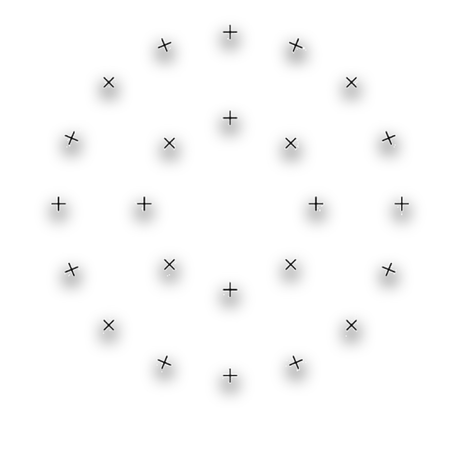
  • The supplied designation identifies a 24-point test array. State whether all points or a selected subset are included in the counting protocol.
Point-Counting Reticles — G55

G55

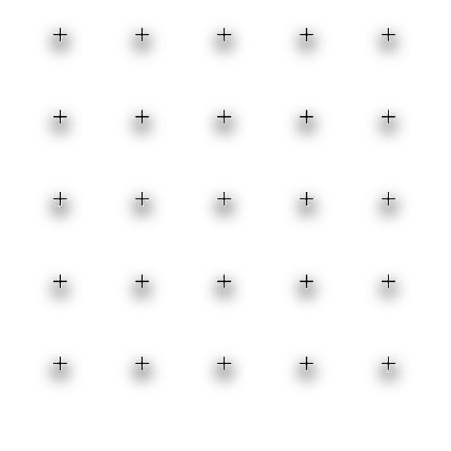
  • The supplied designation identifies a 25-point test array. Keep the point count and sampling field consistent when comparing results.
Point-Counting Reticles — G47

G47

Point-Counting Reticles — NG52

NG52

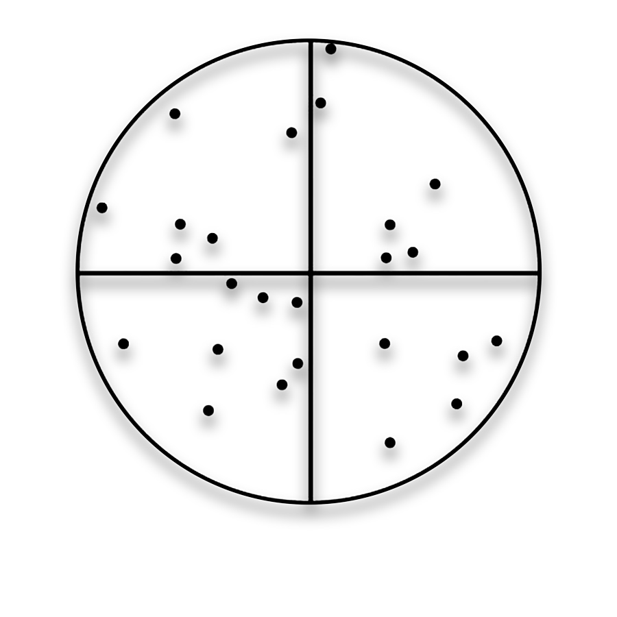
  • The Chalkley point array supports scoring feature occupancy within a field. Define point placement, field orientation and the scoring protocol before comparing observations.
Point-Counting Reticles — G50

G50

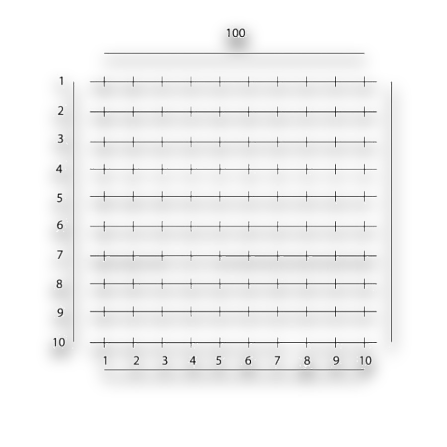
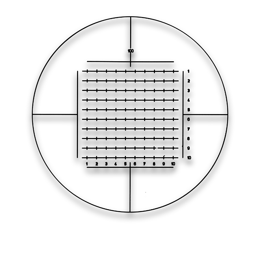
  • The integrating-eyepiece layout provides a rectangular field of repeated marks with labelled axes. Identify which intersections or marks count as sampling points.

Related pattern choices

Selection notes

Point-counting reticles distribute points or intersections for microscopic sampling and area-fraction assessment.

Choose point count and spacing for the sampling method and target scale. Apply a consistent rule for boundary hits.

Information for your inquiry

Point layout, spacing, method, calibrated field, objective and mounting geometry.

Is a denser point pattern always better?

Point count and spacing should fit the method and feature scale. A layout that supports consistent judgement is more useful than density alone.

Search