
Precision Optical Windows
Separate the beam path, mounting boundary and coating requirements so the window can be manufactured, installed and inspected against one drawing.
Design the beam path and mount together
A usable specification separates four things: the outside geometry that fits the housing, the clear aperture that carries the optical requirement, the seal or clamp land that receives mechanical force, and the coating on a named face.
| Boundary | What it controls | What to state |
|---|---|---|
| Outside geometry | Fit, orientation and available mounting space | Diameter or length and width, thickness, radii, holes and edge treatment |
| Clear aperture | The area through which the useful beam passes | Size, position, measured face and optical limits inside the aperture |
| Seal or clamp land | Where the O-ring, adhesive or retaining force acts | Land width, excluded edge zone and support condition |
| Coated area and face | Where transmission, reflection, blocking or conductivity changes | Film function, face, aperture boundary, wavelength band and angle |
Do not use one flatness value to stand in for surface figure, face-to-face parallelism and installed performance. These are different measurements and should be tied to the failure each one prevents.
Window formats and usable aperture
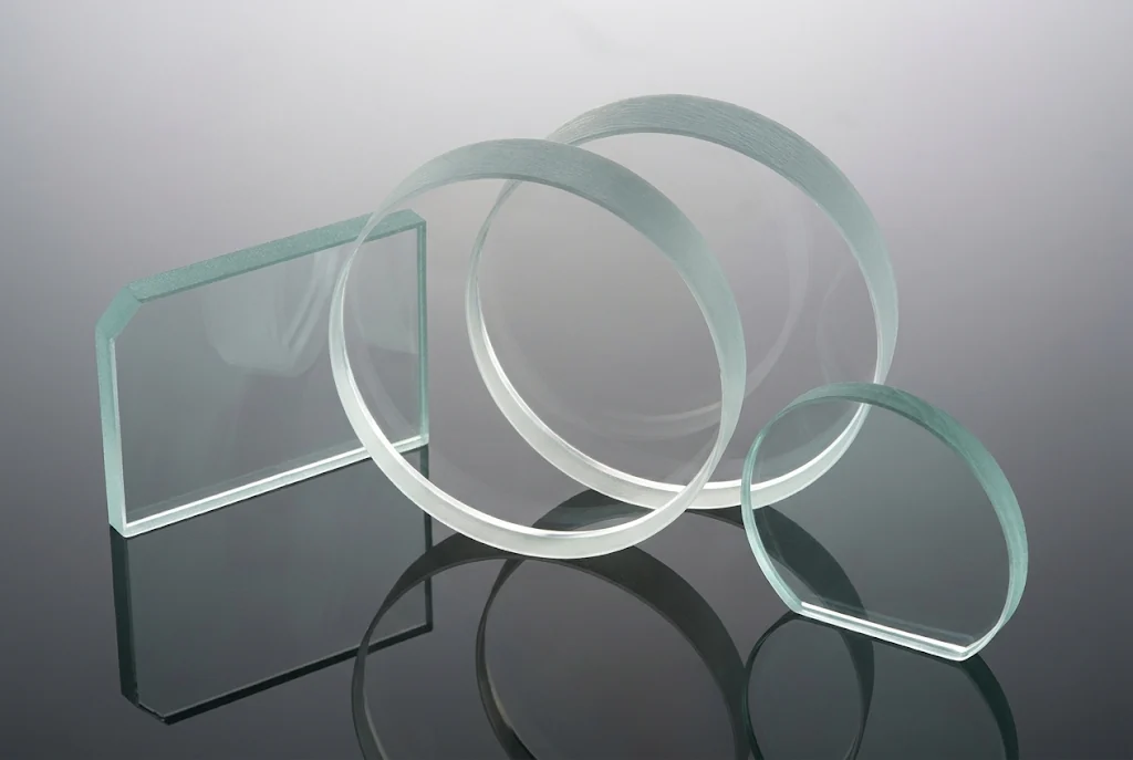
Circular and rectangular windows are common, but the useful optical area is rarely identical to the outside outline. A retaining ring, adhesive bead or O-ring needs its own land outside the beam path. A custom outline may also establish orientation, prevent rotation or clear nearby hardware.
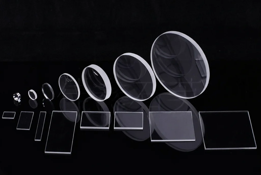
The photograph shows a range of round, square and rectangular formats. It demonstrates available forms, not a catalogue of fixed sizes. Final material, dimensions, surface condition and coating follow the approved drawing.
Flatness and wedge are different
Flatness describes the departure of one face from a reference plane over a stated aperture. It is used when surface or transmitted wavefront matters. Wedge describes the relationship between the front and back faces. Even when both faces are individually flat, a non-parallel pair can act as a weak prism and change beam direction.
A face-to-face difference such as |A − B| only becomes meaningful when the drawing names points A and B and the distance between them. The same thickness difference over a short aperture represents a larger angle than it does over a long aperture. Mounting tilt is another separate term: a parallel plate can leave the outgoing ray parallel while shifting it laterally.
| Property | Published route | How to use it |
|---|---|---|
| Finished thickness | From 0.3 mm on published precision-substrate formats | Confirm material, outline and handling route for the actual drawing |
| Total thickness variation | Up to 2 µm on named substrate routes | State the measured area and sampling method |
| Flatness or surface figure | Format-dependent micrometre limits; λ/4 and λ/2 routes are published | State aperture, test wavelength and support condition |
| Face-to-face thickness difference | |A − B| < 5 µm on a named small-format route | Name points A and B and the distance between them |
| Edge condition | Ground edge and 45° chamfer routes are available | Dimension the chamfer and keep it outside the clear aperture |
These values summarize published supply routes and do not replace feasibility review for a new drawing. A limit applies only with its named material, format, aperture and measurement method.
Coating and mounting complete the design
An uncoated window already reflects at both air-to-glass interfaces. A coating changes that behaviour for a particular function: reduce reflection, block or define an aperture, provide a reflective zone, or add conductivity. Naming only the film material is incomplete; state what the film must do, its wavelength band, incidence angle, face and measurement area.
The mount can also change the delivered result. Clamp force near the clear aperture can bend the glass, while thermal expansion mismatch between the glass and housing can load the seal or change surface figure. If installed performance matters, define whether inspection is performed free, supported or in a representative mount.
Put every decision on one drawing
- Application and beam pathState what the window separates, working wavelength, incidence angle and whether transmitted wavefront or beam pointing is critical.
- Material and thicknessName the exact glass or fused-silica grade, finished thickness and any spectral or thermal reason for the choice.
- Outline and datumsDimension the outside geometry, holes, radii, chamfers and the datums used by the housing.
- Clear aperture and landLocate the optical aperture separately from the seal, adhesive or clamp area and edge exclusion.
- Surface and parallelismState surface quality, flatness or figure, TTV and wedge with their apertures, positions and methods.
- Coating requirementsDefine function, face, coated area, wavelength band, angle, polarisation when relevant and acceptance method.
- Environment and mountingProvide temperature range, pressure direction, cleaning method and whether the part is clamped, bonded or sealed.
- Quantity and recordsState quantity, packaging and the material, dimensional or coating records required with delivery.
Make inspection conditions reproducible
A result can only be compared with a limit when the drawing revision, measured area, support state, instrument and method are known. Record incoming free-part measurements before bonding or clamping when installation may change the glass shape.
| Item | Acceptance condition | Record |
|---|---|---|
| Outline and thickness | Approved drawing, datums and tolerances | Measured dimensions and drawing revision |
| Clear aperture | Named face, aperture and excluded edge | Inspected area and observed defect result |
| Flatness and TTV | Support state, sampling area, method and limit | Measured value, instrument and condition |
| Wedge or parallelism | Two named positions or an angular limit | Position, spacing, result and method |
| Coating | Function, face, wavelength, angle and agreed measurement area | Witness or part result under the stated conditions |
Questions before ordering
Is an optical window the same as a polished glass substrate?
They can begin with the same material, but the acceptance logic differs. A substrate is normally defined as a manufacturing base. A window must also work in an assembly, so clear aperture, wedge, seal or clamp area, coating face and mounted condition may need separate requirements.
Which matters more for beam pointing: flatness or wedge?
They control different errors. Flatness affects surface or transmitted wavefront. Wedge describes the angle between the two faces and can change the outgoing beam direction. A pointing requirement should therefore state wedge or parallelism separately from flatness.
Can a window be supplied without a coating?
Yes. An uncoated window can be supplied when the material, thickness, surface condition and inspection requirements are defined. If transmission or reflection is an acceptance item, the wavelength band, incidence angle and measurement conditions must also be stated.
What information is needed for a first quotation?
Send the outline, thickness, material, clear aperture, working wavelength, coating function, quantity and the most important geometric or optical limit. A preliminary drawing is enough to start feasibility review; the complete inspection plan can be confirmed before production.
Send your window drawing
A preliminary sketch with the outline, clear aperture, material, thickness, wavelength, film function and quantity is enough to begin review. Final tolerances and inspection records can then be aligned with the actual assembly.