
Stitched Large-Format Photomasks: Field Tiling
A 17 in plate is 21.8 mm wider than the largest writing field. How you spend those 21.8 mm decides whether the mask has a seam at all — and if it does, where the seam falls and what has to be measured across it.
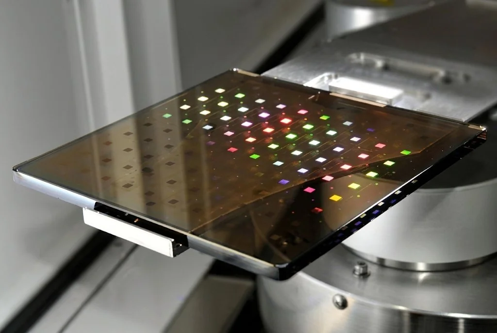
Decide the usable pattern area before the plate
If the active area fits inside one writing field, the mask has no seam and needs no stitching budget. If it does not, the seam position becomes a drawing decision — and the drawing should say where the seam may fall and what step is allowed across it.
A laser direct-write system exposes one field at a time. When the artwork is larger than that field, the pattern is written in several passes and the boundaries between them are seams. Nothing is joined, glued or moved: the substrate stays on the stage and the pattern is simply broken into zones that fit the optics. That makes a stitched mask a normal product rather than a compromise — provided the seams are placed on purpose.
This guide is about the case where the plate is chosen first and the active area then turns out to be slightly too large. That is where most of the avoidable problems come from.
Why a large mask has a seam at all
Two published numbers set the whole question. The largest writing fields are 205 × 205 mm and 410 × 410 mm, depending on the configured writing mode. The largest substrate formats are 9 × 9 in and 17 × 17 in. Convert the formats to millimetres and the gap is small:
- 17 in × 25.4 = 431.8 mm against a 410 mm field leaves 21.8 mm — about 10.9 mm per edge.
- 9 in × 25.4 = 228.6 mm against a 205 mm field leaves 23.6 mm — about 11.8 mm per edge.
In both cases a border of roughly 11 mm per side is all that separates a one-field mask from a tiled one. That border is not waste. It is the strip a plate needs for holding, cleaning and edge exclusion, and on these two formats it and the seam are competing for the same millimetres.
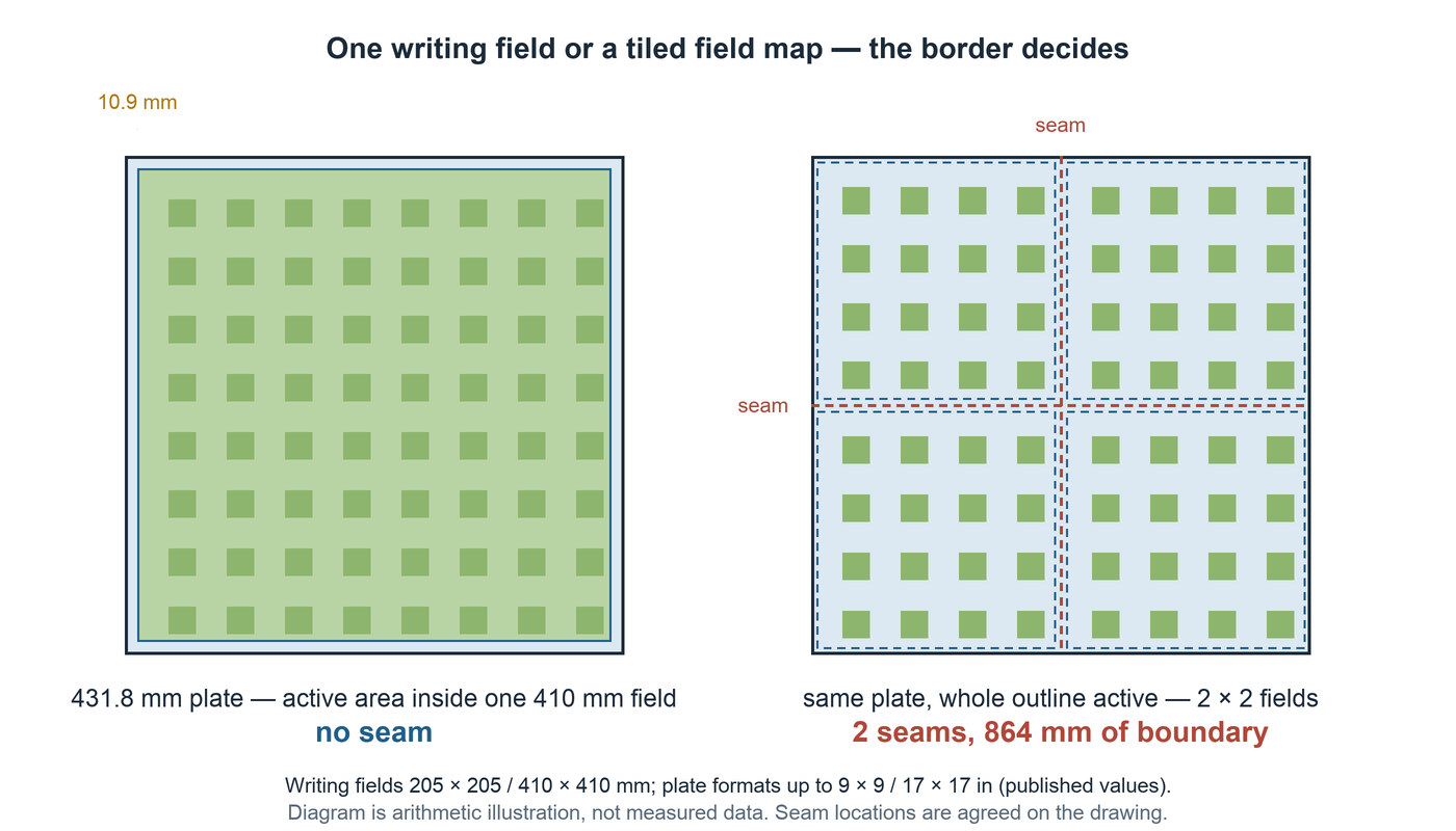
The field map: plate, active area, fields
The table below applies the same arithmetic to every published square format, assuming the worst case where the active area equals the plate outline. Seam length is the total length of internal boundary, not the plate perimeter.
| Plate format | Outline | 205 mm field | 410 mm field |
|---|---|---|---|
| 3 in | 76.2 mm | 1 field, no seam | 1 field, no seam |
| 4 in | 101.6 mm | 1 field, no seam | 1 field, no seam |
| 5 in | 127.0 mm | 1 field, no seam | 1 field, no seam |
| 6 in | 152.4 mm | 1 field, no seam | 1 field, no seam |
| 7 in | 177.8 mm | 1 field, no seam | 1 field, no seam |
| 9 × 9 in | 228.6 mm | 2 × 2, 2 seams (457 mm) | 1 field, no seam |
| 17 × 17 in | 431.8 mm | 3 × 3, 4 seams (1,727 mm) | 2 × 2, 2 seams (864 mm) |
Reading the two highlighted rows: the 9 in plate is a one-field job on the 410 mm field and a four-field job on the 205 mm field, so the same drawing has two different answers depending on the writing mode chosen. The 17 in plate cannot be a one-field job either way unless a border is reserved.
What a seam actually costs
A seam changes the pattern in two separable ways. The position of a feature can shift as it crosses the boundary, and its width can change if the exposure conditions at the end of a field differ from the start of the next. Both are visible under a microscope as a discontinuity, but they are different measurements and they belong to different lines in an inspection plan.
The reason to keep the two apart is that a single global number hides the seam. Full-field registration is measured over the whole active area; a 30–70 nm step confined to one boundary barely moves that average. A mask can pass a global registration check and still fail at the seam, which is why the inspection plan needs both.
The published terms, and what kind of error each one is
The values below are the reference figures published for the three writing configurations. They are equipment reference values used for route selection; the acceptance of a delivered mask is set by the approved drawing.
| Term | Config I | Config II | Config III | Type |
|---|---|---|---|---|
| Stitching stability | 30 nm | 60 nm | 70 nm | Placement — local to a seam |
| 2nd-layer alignment | 225 nm | 225 nm | 350 nm | Placement — between layers |
| CD uniformity | 55 nm | 65 nm | 75 nm | Dimensional — across a field |
| Edge roughness | 30 nm | 40 nm | 50 nm | Dimensional — along an edge |
| Address grid | 12.5 nm | 12.5 nm | 25 nm | Placement resolution |
Stitching is the smallest placement term in that table. It is also the only one that appears as a step at a line somebody chose. The other placement term, second-layer alignment, is an order of magnitude larger and applies between layers rather than inside one — which is why a stitched mask in a single layer and a multi-layer mask set are different sourcing problems. If the pattern is a set of aligned layers, the multi-layer mask set page is the relevant starting point.
A 3σ placement value, a 3σ dimensional value and a grid resolution describe different things and combine only through the specific requirement being tested. Comparing stitching against CD uniformity as if they were one budget produces a number that cannot be verified by any single measurement.
Where a seam may fall
Seam placement is a layout decision, and it is the part of a stitched order that is most often left implicit. Four positions come up repeatedly, and they are not equally safe.
- A scribe lane between pattern cells — routine. Nothing crosses the boundary, so a position step there has no feature to displace.
- The handling border outside the active area — routine, for the same reason.
- Through an alignment fiducial — avoid. The fiducial is the datum later exposures register to; a seam through it changes the reference for every subsequent layer, and the error appears in a place nobody inspects because the mark is assumed to be correct.
- Through a set of continuous parallel lines or a periodic array — agree first. It can be written, but the boundary is where a phase or pitch discontinuity becomes visible; the drawing should state the permitted step and the inspection locations before exposure.
The two routine cases share a property: nothing crosses the boundary. The two difficult cases share the opposite property: something crosses, and the crossing is what the customer measures. If it must cross periodic lines, the drawing should state the permitted step and the inspection locations, and the position should be agreed before exposure.
What the drawing must state
A stitched mask is quoted from the same drawing package as any other mask, plus the information that fixes the tiling. The table below separates the inputs that control manufacture from the ones that only describe intent.
| Drawing input | What it controls | If it is missing |
|---|---|---|
| Plate outline and thickness | Fixture, handling, edge exclusion | The active area is assumed to be the outline, and a seam appears |
| Active area, dimensioned separately | Field count and tiling | The tiling is guessed and may not match the pattern |
| Seam coordinates or seam-free zones | Where each boundary falls | A seam lands where the writer puts it, not where the layout wants it |
| Permitted step at the seam | Acceptance of δ and Δw | The inspection has no limit to compare against |
| Features that must not be crossed | Fiducials, arrays, measurement targets | A datum or a grating can be split |
| Registration requirement, local and global | Inspection locations and method | A single global number reports success |
| Artwork revision and polarity | Film side and transfer direction | A correct-looking mask is written in the wrong orientation |
Two of these are frequently omitted because they feel like manufacturing detail rather than customer requirements: the permitted step and the seam coordinates. Both are customer decisions, because only the designer knows which lines in the pattern can tolerate a boundary.
The general drawing conventions for patterned glass — units, layers, viewing direction, datum definition — are covered in Preparing DWG drawings for patterned glass and are not repeated here.
Inspecting across the seam
An inspection plan for a stitched mask differs from a single-field plan in one respect: the measurement locations are chosen at the boundaries rather than distributed over the area. A workable sequence:
- Confirm the tiling against the drawing.Field count, seam coordinates and the seam-free zones should match before any dimensional measurement is interpreted.
- Measure position step at agreed locations on each seam, on both axes.Pick features that genuinely cross the boundary rather than features near it.
- Measure width step separately.A line can arrive in the right place and the wrong width; combining the two into one figure hides which one moved.
- Inspect the seam ends and field corners.Where two seams meet, both errors are present at once, and this is the least forgiving point on the plate.
- Check the features that were declared un-crossable.Fiducials, alignment marks and measurement targets should be intact and on one side of the boundary.
- Record the method, the locations and the instrument.A step value without a stated measurement location cannot be compared with the next delivery.
Acceptance criteria for a specific order are those written into the approved drawing, purchase order or quality agreement. The wider acceptance framework — defect classification, dimensional verification and record format — is described in Pattern inspection and acceptance.
What is published, and what needs to be agreed
Three kinds of statement appear on this page and they should not be read as one.
- Published capability. Writing fields of 205 × 205 mm and 410 × 410 mm; substrate formats up to 9 × 9 in and 17 × 17 in; thickness 0–12 mm; finished line-width tolerance ±0.2 µm; stitching stability 30, 60 or 70 nm at 3σ by configuration. These are the figures the site publishes today and they are quoted here without extension.
- Arithmetic on those figures. Plate outlines in millimetres, field counts, seam counts and seam lengths in the table, and the 21.8 mm and 23.6 mm margins. These are calculations, not new specifications.
- Agreed in writing. Edge exclusion, permitted step, seam coordinates, inspection locations, defect limits and sampling. None of these has a published default.
Two things this page deliberately does not claim: a maximum plate size beyond 17 × 17 in, and any defect density or yield figure for a seam. Neither is published, and a number invented here would be impossible to verify later.
Common questions
Can you supply a photomask larger than 17 × 17 in?
The published substrate formats are up to 9 × 9 in and 17 × 17 in, with thickness 0–12 mm and other thicknesses on request. Anything larger is a development question rather than a catalogue item. Send the outline, thickness, active area and tiling intent so the route can be reviewed before it is quoted.
Does a stitched mask have worse global accuracy than a single-field mask?
Not necessarily. Tiling changes where an error can appear, not necessarily how large the global error is. A single-field mask can have a global placement error; a stitched mask can have the same global behaviour plus a local step at each seam. That is why global registration and seam continuity should be specified and measured as two separate requirements.
How much border should I leave around the active area?
No default border is published, because handling, fixture and cleaning requirements differ per plate. What can be stated is the arithmetic: a 17 × 17 in plate is 21.8 mm wider than a 410 mm field, so roughly 10.9 mm per edge removes the seam entirely. On a 9 in plate against a 205 mm field the figure is 11.8 mm per edge. The value you actually reserve is agreed on the drawing.
Do I have to supply a tiling plan with the artwork?
No. You can send artwork in one coordinate system and ask for a proposed tiling. What matters is that you approve the seam locations before writing, because the seam position is a drawing decision with inspection consequences, not a manufacturing detail.
Can a seam cross a grating or a periodic array?
It can be written, but the boundary is where a phase or pitch discontinuity becomes visible. Prefer a seam that runs along a cell boundary or a scribe lane. If it must cross periodic lines, the drawing should state the permitted step and the inspection locations, and the position should be agreed before exposure.
How is the seam inspected and recorded?
By measuring across the boundary rather than inside a field: position step and width step at agreed locations on both axes, plus the seam ends where fields meet at a corner. Global full-field registration alone can pass while a local seam step is out of tolerance, so both belong in the inspection plan.
Send the drawing and the active area
Quotation review for a stitched large-format mask starts from the plate outline, the active area and the artwork. If the tiling is not settled yet, say so — a proposed field split can be reviewed together with the pattern. Useful in the first message: plate outline, thickness and material; active area dimensioned separately; artwork file, units and revision; polarity and viewing direction; seam-free zones or a proposed tiling; permitted step and inspection locations.