Lines, dots and grids
Measure selected line widths, spaces, pitch, dot diameters and centre spacing. Identify the edge-detection rule and sampling locations used for the result.

Check the dimensions and details that make the pattern work.
For your reticle, encoder disc or calibration target, we check the selected lines, dots and reference features against the drawing. Dimensional results and annotated images help your receiving team locate and review each inspected feature.
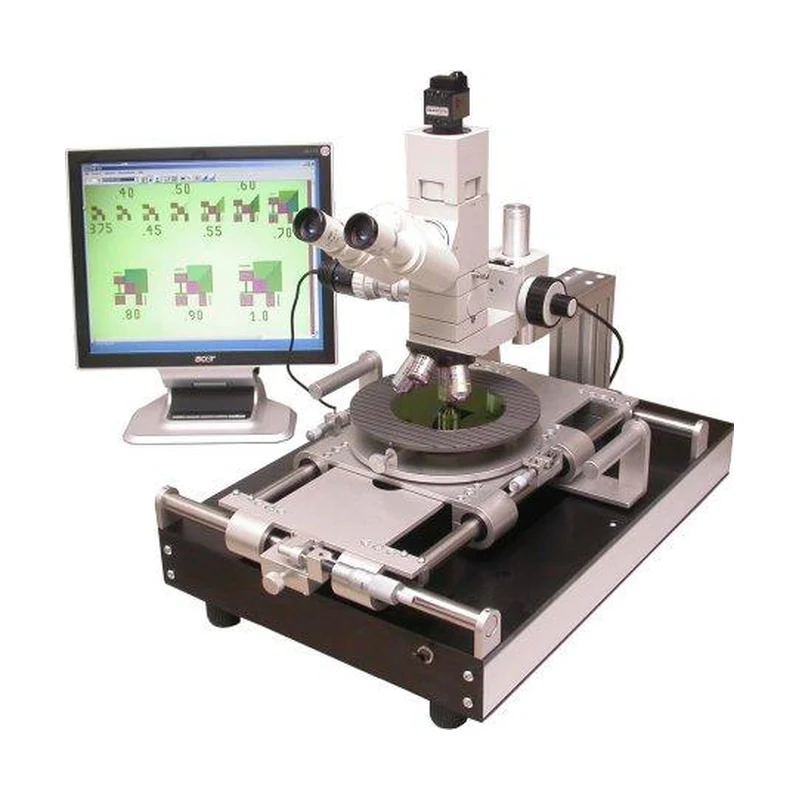
Measure selected line widths, spaces, pitch, dot diameters and centre spacing. Identify the edge-detection rule and sampling locations used for the result.
Compare pattern features with the agreed datum, outside dimensions and reading side. Keep pitch error, feature-size error and pattern-to-part alignment separate.
Review broken or missing lines, pinholes, unwanted material, burrs and visible edge chips under defined illumination and magnification. Record the inspected area.
Connect the reported values with the part or witness piece, measurement positions and drawing revision. Include the required records in the order scope. Review delivery records
Visible crack inspection is a screening method. It does not establish crack depth, edge strength or durability. Strict requirements need a separately agreed test method.
A photograph helps locate and explain a feature. A dimensional result also needs a calibrated measurement method, a datum, units and acceptance limits.
Add height data when a visible feature also needs a step or depth result.
Share the critical acceptance items, required records, quantity and delivery needs. Use your existing drawing for the dimensions already defined.