Steps and etched features
Measure height differences between suitable reference regions, including exposed film steps and etched recesses. Agree the reference planes and the areas used for each result.
Turn surface features into height and profile data.
For suitable patterned or polished parts, we examine the selected step, recess or surface region without stylus contact. A height map and cross-section profiles show where the feature lies and how its height changes.
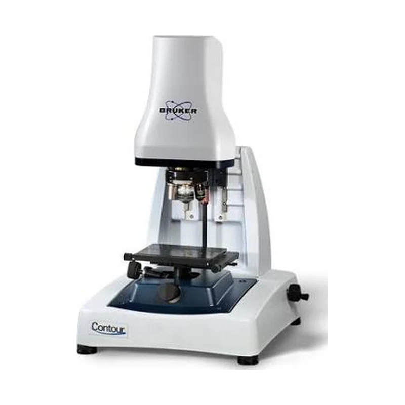
Measure height differences between suitable reference regions, including exposed film steps and etched recesses. Agree the reference planes and the areas used for each result.
Review peaks, pits, grooves and transitions as a height map. Use cross-section profiles to inspect a selected feature and connect it to its location on the part.
Evaluate agreed areal or profile parameters on suitable samples. Define the scan area, filtering and processing before comparing results between parts or batches.
Connect the reported values with the part or witness piece, measurement positions and drawing revision. Include the required records in the order scope. Review delivery records
Transparent layers, steep walls, reflectivity changes and missing optical data can affect the result. Film thickness requires a suitable measurable step or a validated model; a 3D image alone does not establish thickness. Resolution is not the same as measurement accuracy.
An optical profiler obtains non-contact height data over a surface area. A stylus profiler measures along a contact scan path. Material, geometry and the required result determine which method is suitable.
Check overall surface figure when the requirement extends beyond a local scan.
Connect height features with pattern dimensions and visible defects.
Share the critical acceptance items, required records, quantity and delivery needs. Use your existing drawing for the dimensions already defined.