Start with the analysis method
State whether the image will be evaluated by slanted-edge SFR, periodic line pairs, a Siemens star, a USAF reading or a combined workflow.

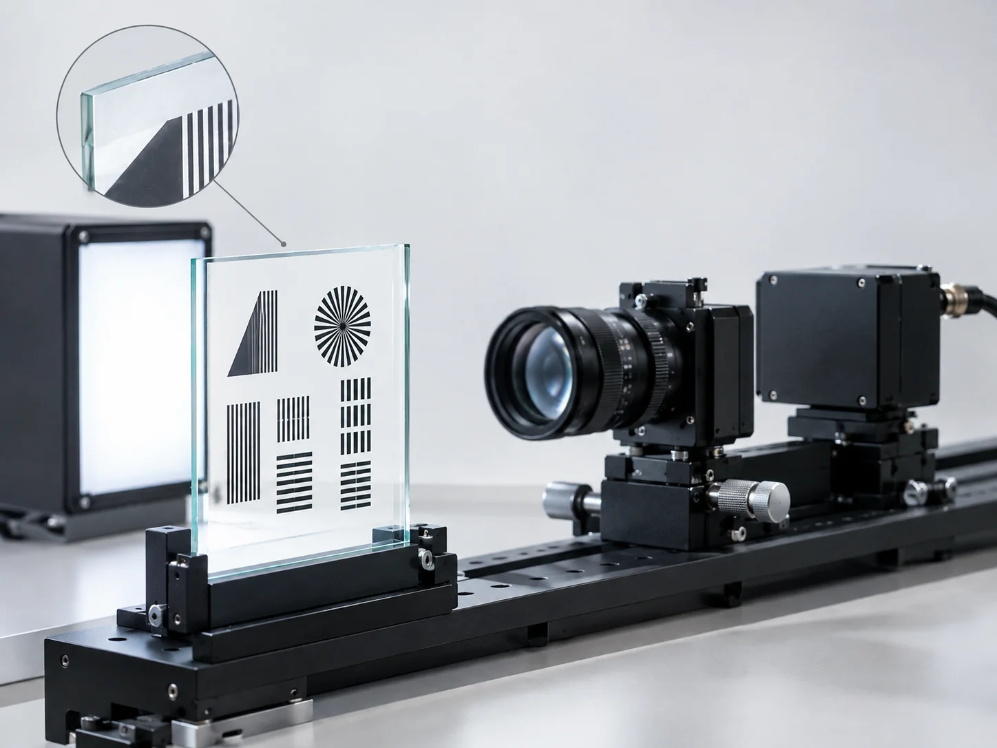
Custom chrome-on-glass MTF reticles combining slanted edges, line pairs, Siemens stars, resolution patterns and alignment marks for optical imaging tests.

A Glass MTF Reticle is a drawing-defined optical test plate carrying the patterns required by a particular imaging and analysis workflow. Pattern geometry, substrate, polarity, illumination and inspection criteria are reviewed together.
Choose this product when several MTF, resolution or alignment features need to share one glass plate. For a single established method, a dedicated slanted-edge, Siemens-star or USAF target may be simpler.
State whether the image will be evaluated by slanted-edge SFR, periodic line pairs, a Siemens star, a USAF reading or a combined workflow.
Define the active regions, feature directions, field positions, alignment references and clear space needed by the camera and software.
Separate feature size, pattern placement, edge condition and optical defects so each requirement has a clear inspection method.
| Pattern | What it helps measure | Define before manufacture |
|---|---|---|
| Slanted edge | What it helps measureSoftware-derived SFR or MTF from an imaged edge. | Define before manufactureDefine edge angle, usable length, contrast, region of interest and analysis method. |
| Line pairs | What it helps measurePeriodic response checks at known target-plane frequencies. | Define before manufactureDefine line and space width, pitch, duty cycle, direction and active area. |
| Siemens star | What it helps measureFocus and directional comparison across changing radial detail. | Define before manufactureDefine sector count, active diameter, central exclusion region and waveform. |
| USAF 1951 | What it helps measureGroup-and-element readings for discrete resolution comparison. | Define before manufactureDefine group range, polarity, chart scale, orientation and reading conditions. |
| Grid | What it helps measureImage scale, distortion and field mapping with distributed references. | Define before manufactureDefine pitch, line width, orthogonality, origin and position tolerances. |
| Custom marks | What it helps measureAlignment, positioning and software recognition within the test field. | Define before manufactureDefine mark geometry, coordinates, polarity, datums and recognition rules. |
For equal line and clear-space widths, the period is twice the line width. Target-plane spatial frequency is 1000 divided by the period in micrometres. Magnification, sensor sampling and the analysis method still determine what the complete system measures.
Spatial frequency (lp/mm) = 1000 ÷ period (µm)
| Line width | Clear space | Period | Target-plane frequency |
|---|---|---|---|
| 10 µm | Clear space10 µm | Period20 µm | Target-plane frequency50 lp/mm |
| 5 µm | Clear space5 µm | Period10 µm | Target-plane frequency100 lp/mm |
| 4 µm | Clear space4 µm | Period8 µm | Target-plane frequency125 lp/mm |
| 2 µm | Clear space2 µm | Period4 µm | Target-plane frequency250 lp/mm |
| 1 µm | Clear space1 µm | Period2 µm | Target-plane frequency500 lp/mm |
Minimum feature, dimensional tolerance and pattern position are quoted after the geometry, substrate and inspection method are reviewed.
| Item | Confirmed configuration |
|---|---|
| Product type | Confirmed configurationCustom chrome-patterned glass reticle |
| Pattern options | Confirmed configurationSlanted edge, line pairs, Siemens star, USAF 1951, grids, crosshairs and custom marks |
| Substrate | Confirmed configurationSoda-lime glass or fused silica, selected for the application |
| Optical mode | Confirmed configurationTransmissive or reflective configuration to drawing |
| Pattern polarity | Confirmed configurationChrome features on a clear field or clear features in a chrome field |
| Dimensions and tolerances | Confirmed configurationConfirmed against the approved drawing and inspection method |
Soda-lime glass or fused silica can be reviewed according to wavelength, size, thermal conditions, mounting and flatness requirements.
A practical option for many visible-light tests when size, flatness, transmission and thermal conditions are compatible.
Consider it when lower thermal expansion, UV transmission or another grade-specific optical property matters to the setup.
Combine MTF, resolution and alignment patterns on one drawing-defined glass reticle.
Inspect the agreed critical dimensions, pitch, edge condition, pattern position, polarity and clear-area cleanliness. Optical density, transmission, flatness or surface requirements are included only when defined in the approved specification.
Clarify what the physical target defines and what still belongs to the complete imaging system.
An MTF or SFR result requires a defined measurement method. A resolution target is often read by identifying distinguishable bars or features. One custom glass reticle can include both types, but each region keeps its own reading rule.
It defines a physical target-plane frequency of 500 lp/mm. Magnification, pixel sampling, optics and the analysis method determine the frequency and response measured by the complete imaging system.
Yes. Slanted edges, line pairs, stars, grids and alignment marks can share one drawing when each region has enough usable area and remains compatible with the capture and analysis workflow.
Choose from the operating wavelength, thermal conditions, target size, mounting, flatness and cost constraints. The material name alone does not establish the finished pattern tolerance.