Pitch and line geometry
Specify pX and pY separately. For each axis, define line width, clear spacing and whether the duty cycle refers to the opaque or transparent portion. State the viewing direction and film side to avoid mirrored coordinates.

Drawing-defined X/Y patterns on glass provide a planar reference for compatible two-axis optical position readers. TL OPTIK supplies the patterned glass component, with pitch, active area and datums reviewed around your reading architecture.
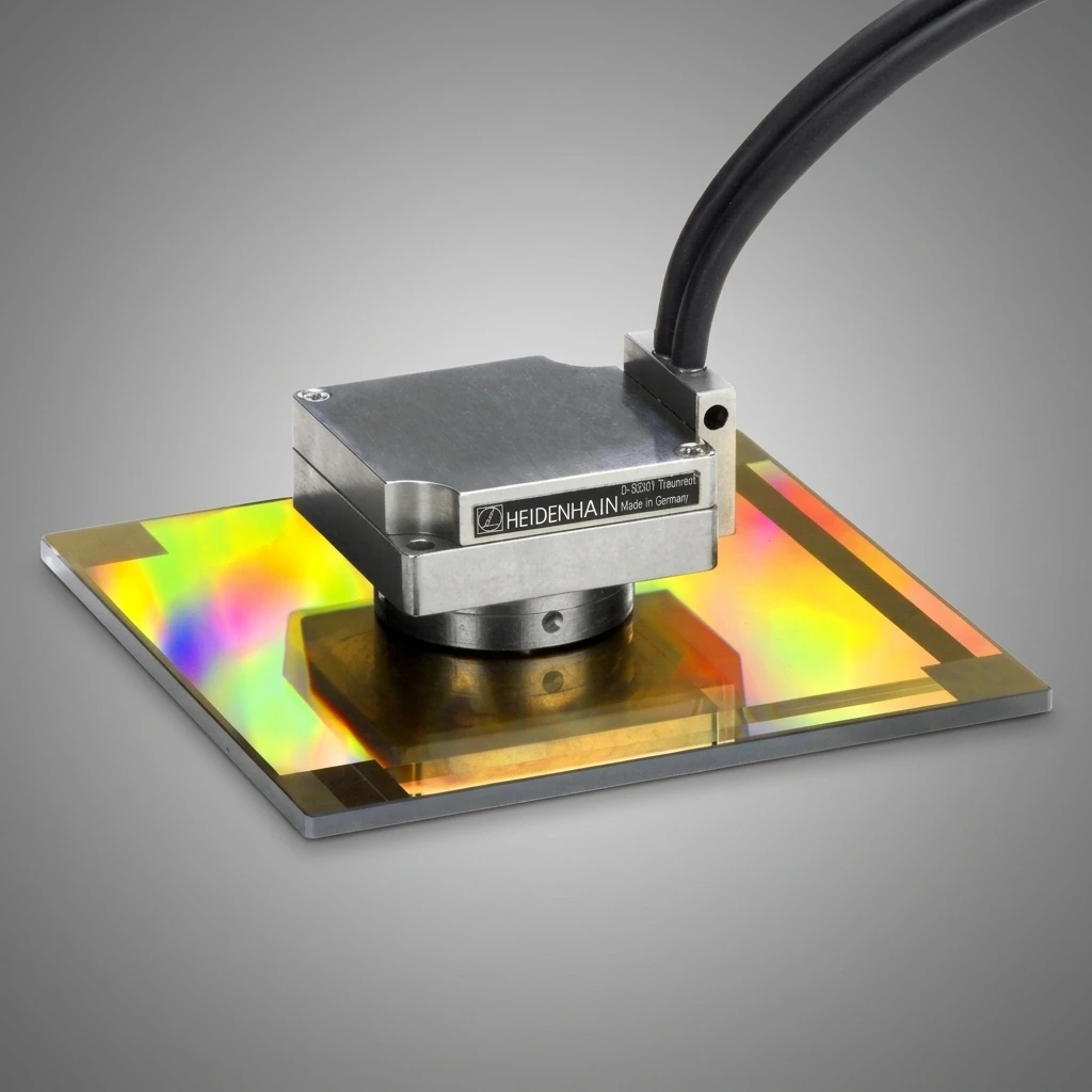
Define the geometry and acceptance conditions together. Values are confirmed against the artwork and reading requirements, rather than one universal pitch or accuracy claim.
| X and Y pitch | Specify pX and pY independently, including units and tolerance; equal pitch is not assumed. |
|---|---|
| Line width and duty cycle | Define opaque line width, clear spacing and the duty-cycle convention for each axis. |
| Orthogonality and placement | Define the X/Y angle, coordinate origin and pattern position relative to mounting datums. |
| Active area and references | State patterned width and height, edge exclusions, reference marks and their coordinates. |
| Glass substrate | Review optical glass or fused silica against wavelength, dimensions and thermal requirements. |
|---|---|
| Outline and mounting | Specify overall dimensions, thickness, edge finish, support area and fixation method. |
| Flatness and film side | Define the evaluation area, measurement support and pattern-side orientation. |
| Optical pattern | Chrome amplitude patterns are reviewed to drawing. Transmission or reflection requirements must include the wavelength and reading geometry; phase-relief structures require separate feasibility review. |
| Local pattern dimensions | Agree line-width and pitch sampling positions, inspection method and acceptance limits. |
|---|---|
| Coordinate accuracy | Specify cumulative position error, X/Y orthogonality and datum registration over the agreed region. |
| Defects and documentation | Agree limits for missing features, pinholes, scratches and contamination, plus drawing revision and report scope. |
| Measurement conditions | State reference temperature, support conditions and any required uncertainty or traceability documentation. |
A cross grating scale describes a pattern with two periodic directions. To use it as an XY encoder scale, the reader must distinguish movement in each direction. Orthogonal lines alone do not specify the optical method or guarantee a usable two-axis signal.
Specify pX and pY separately. For each axis, define line width, clear spacing and whether the duty cycle refers to the opaque or transparent portion. State the viewing direction and film side to avoid mirrored coordinates.
Locate the coordinate origin and reference marks from mechanical datums. Patterned area, glass outline and usable travel are different dimensions: the sensing footprint and edge exclusions reduce the region in which the reader can operate.
A planar scale places both coordinate references on one substrate. Specify the relationship between the axes, the usable two-dimensional field and the reader footprint. The readhead design determines which pattern structure is suitable.
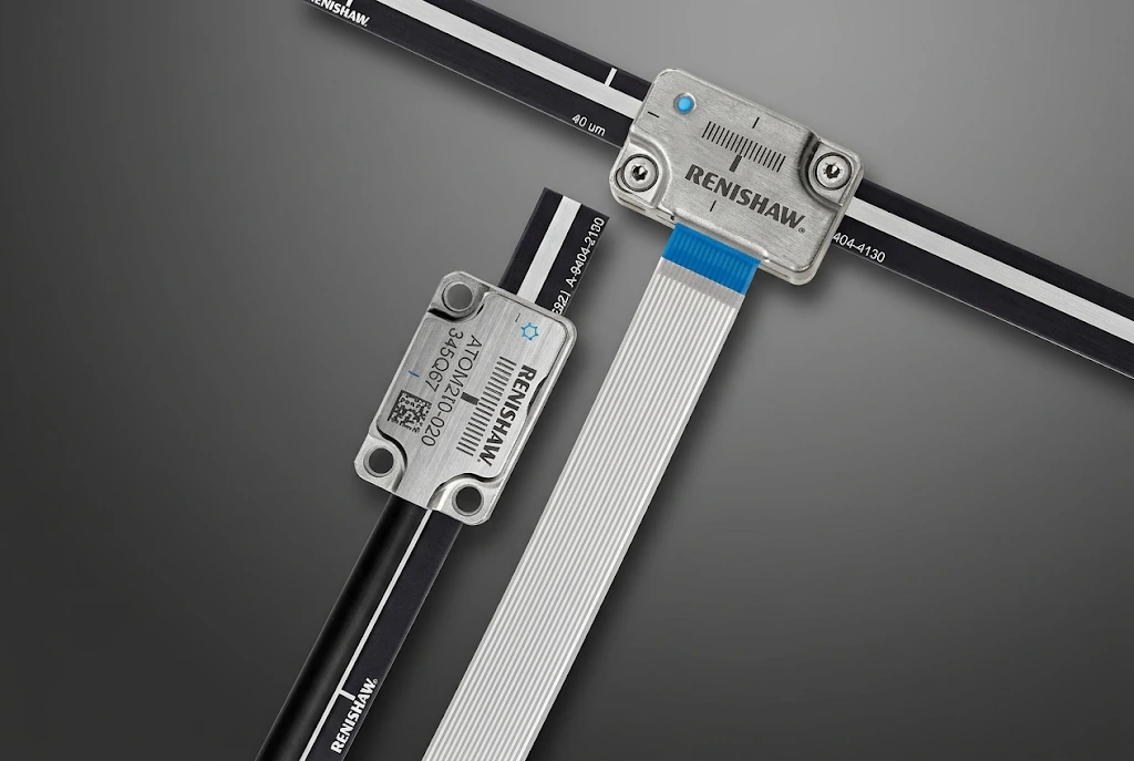
Two linear scales provide separate references. Machine geometry, axis squareness and sensor placement must be assessed independently. A photograph of two scales does not establish the accuracy of the combined XY stage.
Potential projects include precision XY stages, optical metrology and semiconductor positioning or inspection equipment. Select the scale from the actual feedback architecture and operating environment.
A local line-width measurement cannot establish coordinate accuracy over the full field. Agree sampling positions, cumulative pattern-placement error and X/Y orthogonality. Axis-angle error can couple movement in one direction into the other coordinate.
Pitch is a physical pattern dimension. Display resolution depends on the reader and interpolation. System accuracy additionally depends on scale errors, mechanics, temperature and calibration; a fine pitch is not a system accuracy specification.
Provide wavelength, transmission or reflection mode, illumination, sensing window and installed gap. Chrome amplitude grids and phase or diffraction structures are not interchangeable simply because their pitches match.
Material expansion changes the coordinate scale with temperature. Clamping, bonding or uneven support may distort the substrate. Define the reference temperature and inspection support, then validate the installed system under its operating conditions.
Provide artwork, X/Y pitches, active area, substrate dimensions, mounting datums, optical mode and quantity. Include readhead information and the target travel.
Resolve polarity, orientation, origin and reference marks. Agree critical tolerances, measurement conditions, sampling locations and the report scope before manufacturing.
Inspect the physical scale against the drawing. The customer then evaluates signal quality and two-axis response using the intended reader, electronics and mounting arrangement.
Record the approved artwork, datums and acceptance limits. Keep component inspection separate from the customer’s complete-system performance validation.
A 2D optical encoder scale provides a positional reference for a compatible optical reader and position-processing system. A camera calibration target supplies known image features for estimating camera geometry or image scale. Similar-looking grids are not interchangeable without a system-level review.
The drawing can specify different pitches. Both pitches, feature polarity and sensing windows must match the intended reading architecture; manufacturing feasibility is reviewed for the complete artwork.
A repeating grid alone does not uniquely identify a position across the whole area. Homing, reference marks or an additional defined code may be needed. Adding a zero mark does not by itself make a scale an absolute encoder.
Compatibility must be reviewed from the readhead requirements and confirmed with the intended optical and mechanical arrangement. Pitch alone is insufficient. Photographs on this page illustrate reading arrangements and do not establish compatibility with the pictured brands or models.
Send the artwork and revision, X/Y pitches, line widths, active area, substrate outline, mounting datums, optical mode and critical tolerances. Include the required quantity and available readhead information. Preliminary drawings can start a review; approved geometry and acceptance criteria are needed before manufacturing.