Measuring grating
Define active length, physical pitch, reference position, pattern direction and the relationship to the mounting datum.

Custom chrome-on-glass moiré gratings, scanning gratings and crossed patterns. Define pitch, duty cycle, active area and matching requirements.
Drawing-defined patterned glass
TL OPTIK manufactures drawing-defined chrome-on-glass gratings for moiré reading, including linear measuring gratings, scanning gratings and crossed two-dimensional patterns. Pitch, line width, active area and mechanical datums are defined around the customer’s reading architecture.
Specify whether the requested part is the measuring grating, scanning grating or a matched pair. For two-dimensional work, define both axes and their relationship to the mechanical origin.
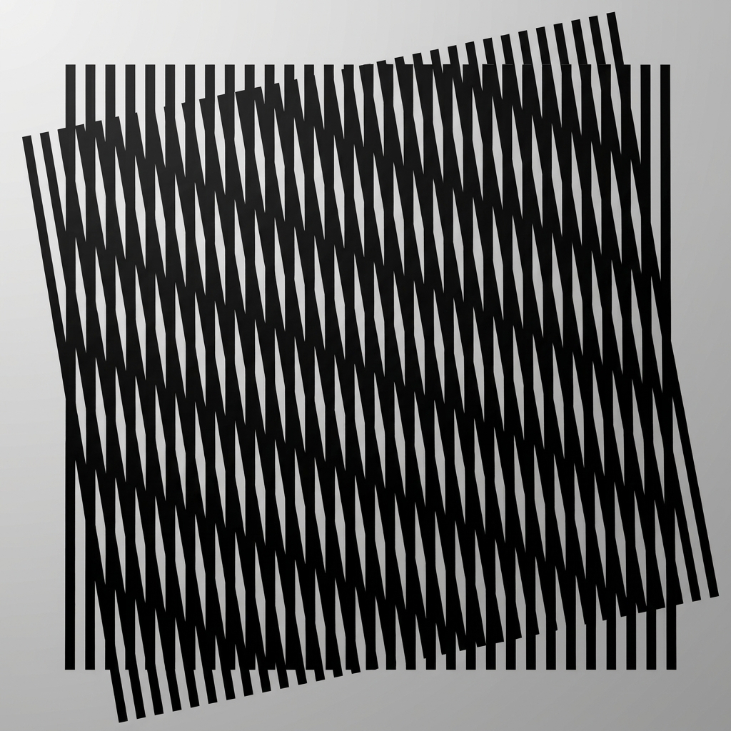
The measurement grating provides the positional reference. The scanning grating participates in signal formation at the reader. Relative movement changes the detected optical signal, which the customer’s detector and electronics convert into position.
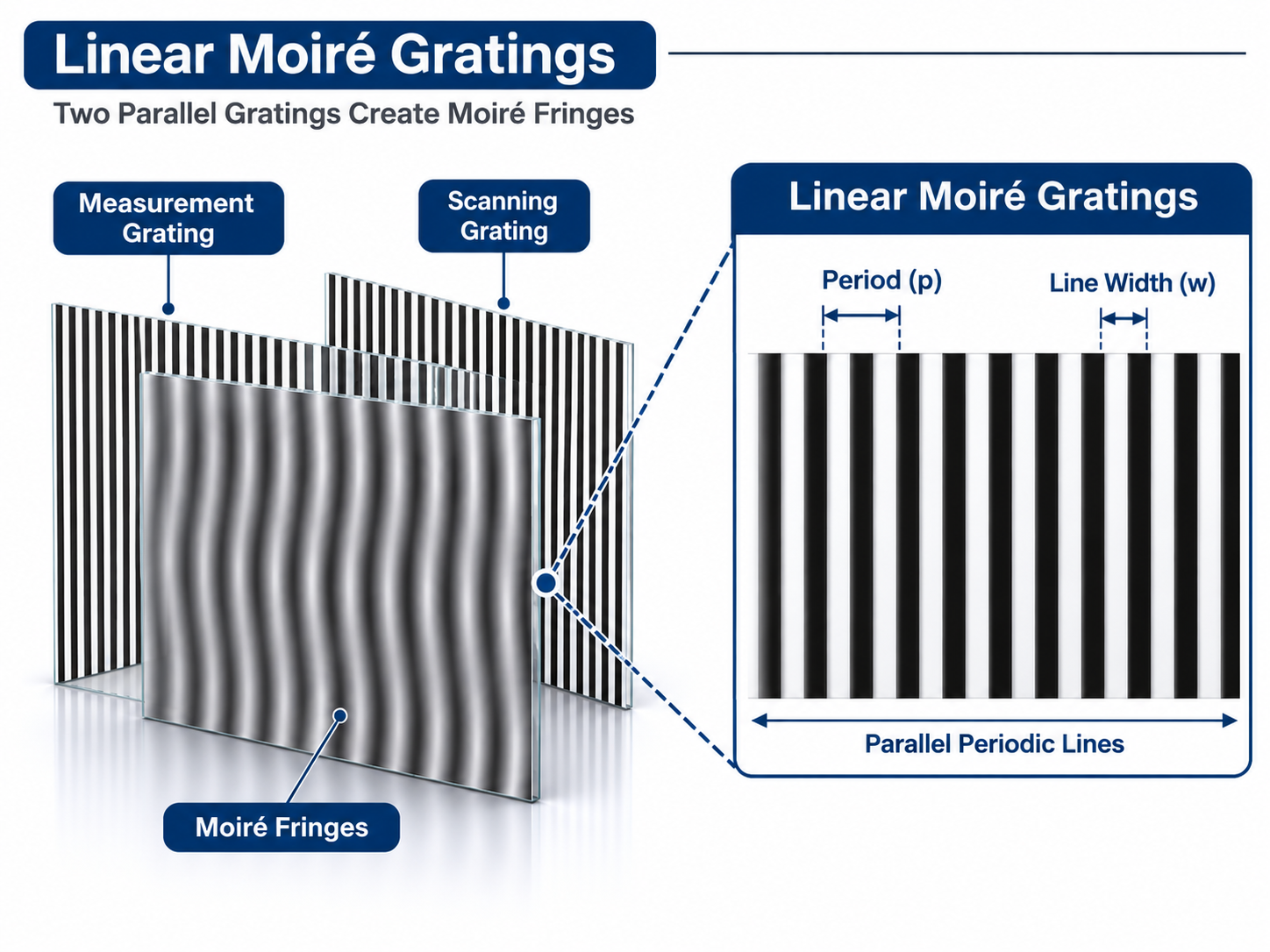
Define active length, physical pitch, reference position, pattern direction and the relationship to the mounting datum.
Define the reader-side sensing window, pitch, line width, film-side orientation and installed relationship to the measuring grating.
Equal nominal pitch alone does not guarantee a compatible pair. Review the two drawings and the installed optical relationship together.
This is a drawing-defined product family. Values are reviewed against the customer’s reader architecture; the page does not apply one generic pitch or tolerance to every project.
| Component role | Measuring grating, scanning grating, index grating or a drawing-defined matched pair |
|---|---|
| Pattern type | Linear periodic lines, crossed gratings or two-dimensional grids |
| Measuring-grating pitch | Defined from the approved artwork and reading architecture |
| Scanning-grating pitch | Defined separately; equal pitch is not assumed |
| Line width and clear spacing | State opaque line width and clear spacing independently where critical |
| Duty-cycle convention | State whether duty cycle uses opaque width or clear width divided by one complete period |
| Active area | Length, width, edge exclusion and sensing window to drawing |
| Orientation and datums | Pattern direction, film side, origin and mechanical reference features |
| Substrate and outline | Glass material, overall dimensions, thickness, edge finish and mounting features |
| Optical conditions | Transmission or reflection, wavelength, illumination, gap and detector arrangement |
| Reference marks | Zero marks, fiducials, index features and their relationship to the active pattern |
| Geometric acceptance | Pitch, line width, pattern position, X/Y angle and defect limits to the agreed drawing and inspection method |
Geometric moiré reading and diffractive or interference-based reading architectures are not interchangeable terms. Identify the actual optical method so the component and test plan can be reviewed correctly.
Linear configuration
Linear configurations use periodic patterns along one measurement direction. The measuring grating defines the active length, pitch and reference position; the scanning grating is defined around its sensing window. Pair review should cover both pitches, line widths, film-side orientation and installed gap.
Crossed and two-dimensional configurations
For a crossed or 2D grating scale, state X and Y pitch separately, even when they are nominally equal. Define the cross angle or orthogonality, the coordinate origin, the pattern-to-datum relationship and whether the project uses one crossed pattern or two interacting grating components.

System integration boundary
These patterned glass components can support optical encoder development, precision linear stages, optical metrology and alignment research. Pitch, displayed subdivision and complete-system accuracy are separate quantities. Pattern quality, reader architecture, installation, thermal conditions and signal processing all contribute to the installed result.
TL OPTIK supplies the drawing-defined patterned glass grating components, not the complete readhead, electronics or control system.
Matched measuring, scanning and crossed grating components for compatible optical readers.
Measuring and scanning gratings reviewed as a matched installed relationship.
The grating is one component inside the reading system. These boundaries prevent a pattern specification from being mistaken for a complete encoder guarantee.
Yes. State that the requested part is the scanning or index grating and provide the mating measuring-grating pitch, installed relationship and optical conditions needed for compatibility review.
No. Line width, duty-cycle convention, relative angle, gap, film-side orientation, sensing window and illumination or detector geometry can all affect the signal.
No. TL OPTIK supplies the drawing-defined patterned glass components. The customer integrates the readhead, illumination, detector, electronics, mechanics and control system.
It can begin with preliminary information, but manufacturing and acceptance require an approved artwork and drawing that define the pattern, datums, polarity, orientation and critical tolerances.
Agree how the physical pattern will be measured before adding any matched optical test. The inspection method should follow the function of each grating and the drawing-defined datums.
Inspect pitch, line width, clear spacing, pattern position, active-area limits, reference marks and visible defects against the approved drawing. For crossed or two-dimensional patterns, include X/Y pitch, angle or orthogonality and origin registration. Matched optical testing is meaningful only when illumination, wavelength, grating gap, relative angle, detector geometry and the acceptance signal are defined.
Send the available drawing, artwork, sample information or preliminary reading architecture. We will first identify the component role and the missing inputs needed for a manufacturable specification.
Discuss your grating design