
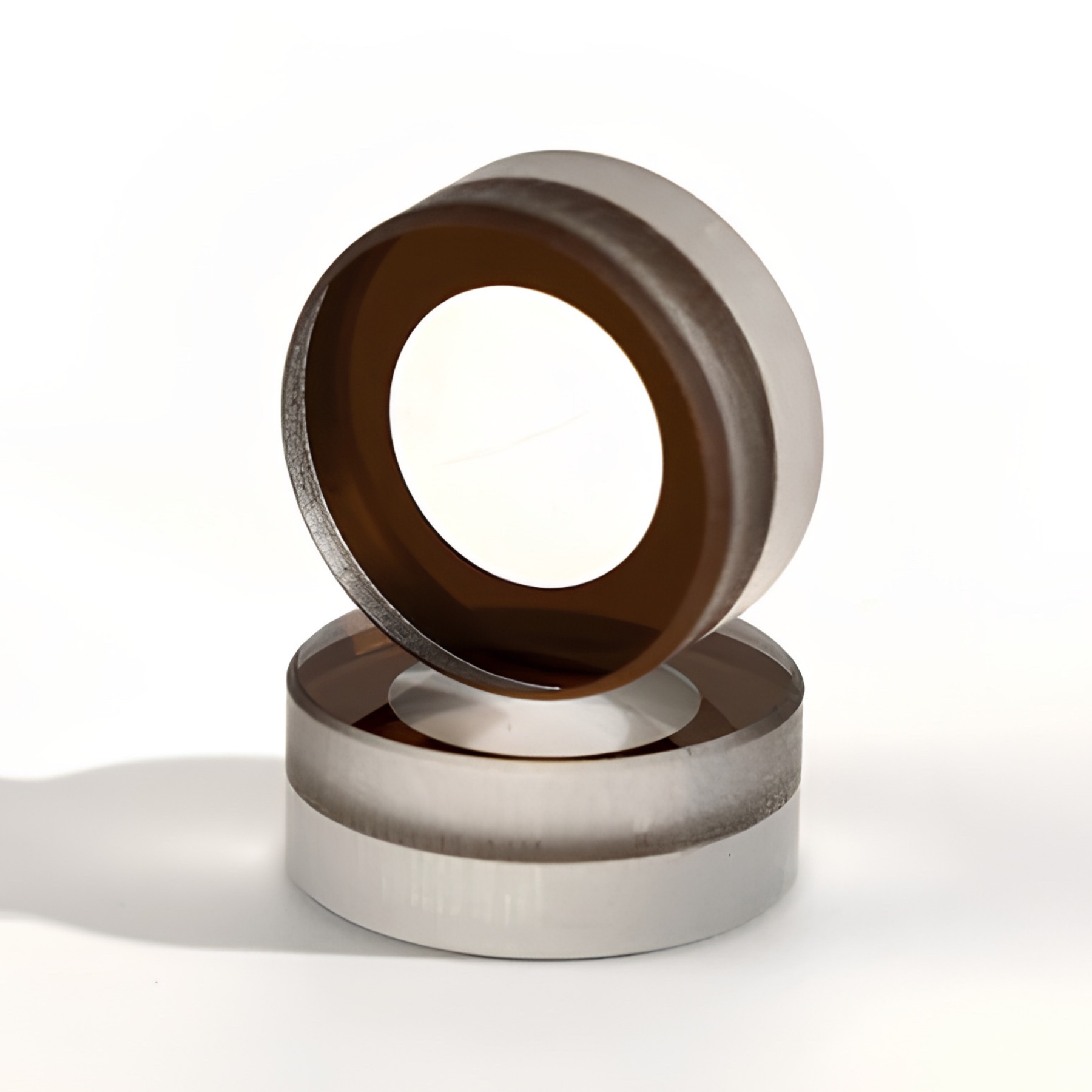
A protected internal reference pattern supplied as a bonded component for the instrument focal plane.
Bonded Glass Reticles
Custom bonded glass reticle assemblies with protected internal patterns. Typical Ø6–10 mm formats and 3–8 µm lines; dimensions and glass stack to drawing.

Protected internal focal-plane pattern
Finished reticle assembly
A fine reticle pattern is enclosed between two glass elements, reducing direct contact with the patterned surface during assembly, cleaning and routine handling. The finished component is supplied as a bonded assembly rather than a single patterned plate.
Choose a bonded construction when the instrument needs an internal focal-plane reference and a protected pattern surface. A single glass reticle may be more suitable when the pattern must remain exposed or the optical and mechanical stack cannot accept the bonded thickness.
Specify the finished assembly
Bonded glass reticles enclose the reference pattern between two glass elements. For a surveying instrument reticle, the glass stack and internal pattern must be specified together with the optical and mounting requirements.
The finished component encloses the pattern between two glass elements. Surveying and optical instrument projects are configured to the instrument drawing, including pattern position and the final assembly thickness.
| Typical outside diameter | Ø6–10 mm; custom dimensions available |
|---|---|
| Common glass combinations | 1.5 + 1.5 mm or 2 + 2 mm; finished thickness includes the bond |
| Typical internal lines | 3–8 µm, selected for the measurement magnification |
| Drawing acceptance | Pattern-to-datum position, clear area, orientation and bond appearance |
Does an enclosed pattern guarantee a hermetic seal?
No. Environmental, bond durability and sealing requirements must be specified and validated separately for the finished component.
For total station, theodolite or optical level reticle enquiries, provide the instrument drawing, finished thickness, pattern geometry and viewing orientation. A custom component is evaluated to drawing; compatibility with a named instrument is not assumed.
Construction choice
Why enclose the pattern?
The bonded construction protects the patterned plane from direct wiping and handling while creating a single component for mounting. It is useful when the pattern belongs at an internal image or focal plane and the mechanical stack is designed for the assembled thickness.
It does not remove the need to define focus, viewing direction or assembly dimensions. These conditions must be agreed with the instrument drawing.
Typical configuration
Dimensions are confirmed as an assembly
The values below describe common starting configurations. Final dimensions, tolerances and inspection points follow the approved drawing.
| Construction | Two glass elements with the reticle pattern enclosed inside the bonded assembly |
|---|---|
| Typical outer diameter | Ø6–10 mm |
| Common glass combinations | 2 mm + 2 mm or 1.5 mm + 1.5 mm |
| Finished thickness | Confirmed from the glass stack, bonding layer and approved drawing |
| Typical internal line width | 3–8 μm, selected for the magnification and viewing requirement |
| Pattern and dimensions | Custom to the approved drawing |
Typical pattern options
Start from an existing pattern or provide your own drawing
These four images show common internal reticle layouts. Pattern dimensions, line width, reference positions and orientation are defined for the actual instrument.
Optical fit
Match line width to magnification
A typical internal line width is 3–8 μm. This is a selectable feature range rather than a tolerance statement. The suitable value depends on magnification, focal-plane location, field of view, illumination, contrast and the observation task.
Provide the optical layout or the working magnification when available. The review should confirm that the line remains readable in the assembled instrument instead of choosing the smallest possible feature.
Where this product is used
Define with the drawing
Geometry and instrument interface
- Outer diameter, element thicknesses and finished assembly thickness
- Pattern drawing, revision, line width and reference geometry
- Viewing direction, focal-plane position and mounting datums
- Quantity, inspection points, packaging and required records
Inspection and delivery
Define acceptance criteria
Acceptance can include pattern completeness, agreed line width and position, assembly dimensions, edge condition, and visible bubbles or inclusions in the defined inspection area. The drawing and agreed inspection method remain the acceptance basis.
Optical glass grade, element thickness, edge finish and bonding requirements are reviewed against the optical path and mounting design.
Technical guidance
Specify the assembly before production
Common questions
Confirm the optical and mechanical stack together
How is a bonded reticle different from a single glass reticle?
The patterned plane is enclosed between two glass elements and the part is delivered as an assembled component. A single glass reticle leaves the patterned surface on one face of one plate.
Is 3–8 μm a manufacturing tolerance?
No. It is a typical internal line-width range. Dimensional tolerance and the inspection method are confirmed separately for the approved drawing.
How should the line width be selected?
Select it with the instrument magnification, focal plane, field of view, illumination and the way the operator must see or measure the pattern. The finest line is not automatically the most suitable line.